Bone length determination

a technology of bone length and measurement method, applied in bone drill guides, applications, surgery, etc., to achieve the effect of increasing or decreasing the size of the bone model

Active Publication Date: 2016-12-08
STRYKER EURO OPERATIONS HLDG LLC
View PDF0 Cites 14 Cited by
  • Summary
  • Abstract
  • Description
  • Claims
  • Application Information

AI Technical Summary

Benefits of technology

[0022]According to yet another embodiment, the method further comprises the step of adapting a bone model so that the bone model corresponds to the imaged bone. Also here, the bone model may be stored in a database. In this case, the bone model may be generated by forming an average of a plurality of previously generated 3D images. To adapt the bone model to the imaged bone, substantially the size of the bone model may be increased or decreased so as to fit to the size of the bone as measured in the image, with shape relations being constant.
[0023]An improved result may be achieved based on a second X-ray image generated from a second imaging direction. Accordingly, the method may furt

Problems solved by technology

But this is difficult, since the bone of

Method used


Image

  • Bone length determination
  • Bone length determination
  • Bone length determination

Examples


Embodiment Construction

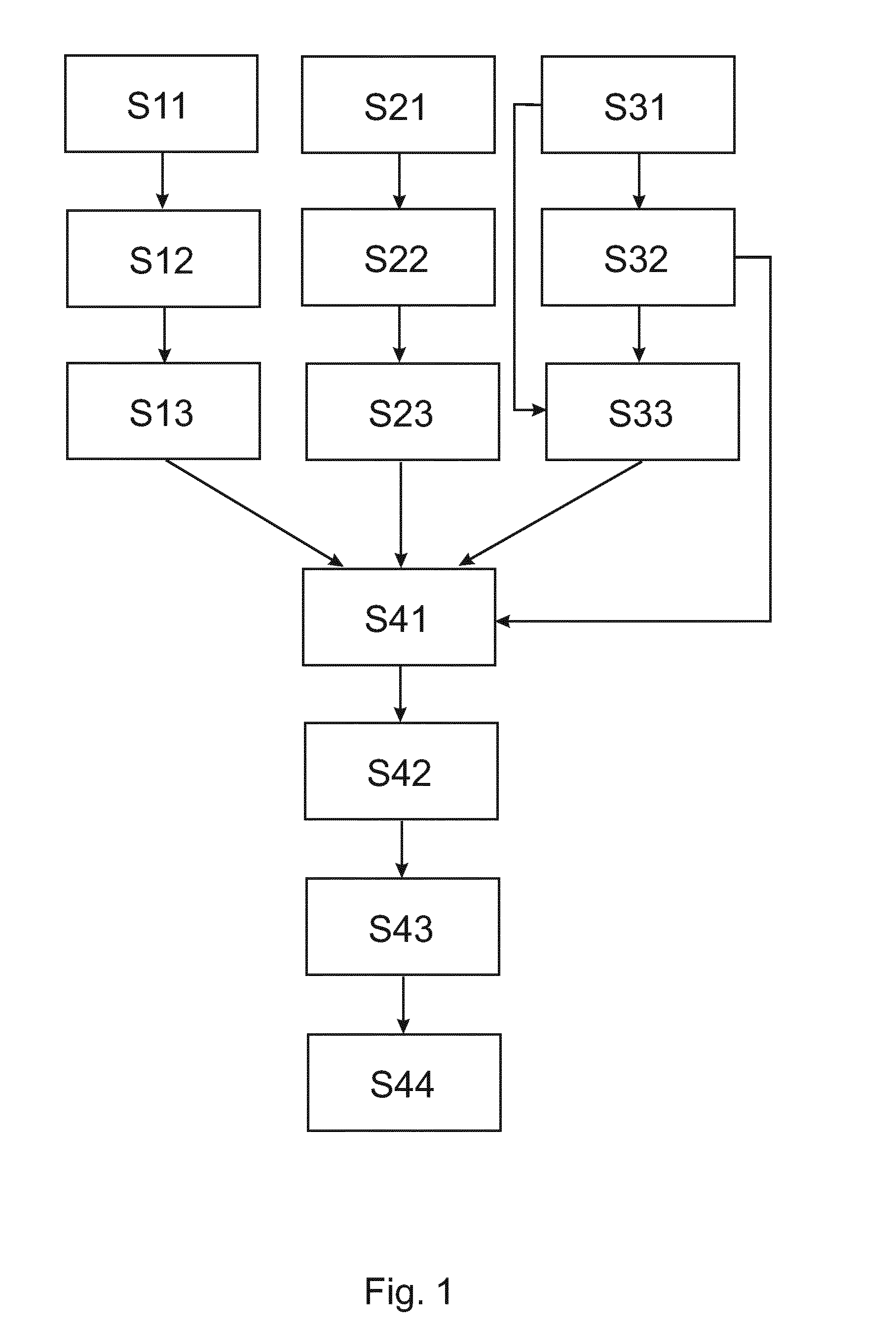
[0044]The flow-chart in FIG. 1 illustrates the principle of the steps performed in accordance with one embodiment of the disclosed method. It will be understood that the steps described, are major steps, wherein these major steps might be differentiated or divided into several sub-steps. Furthermore, there might be also sub-steps between these major steps.

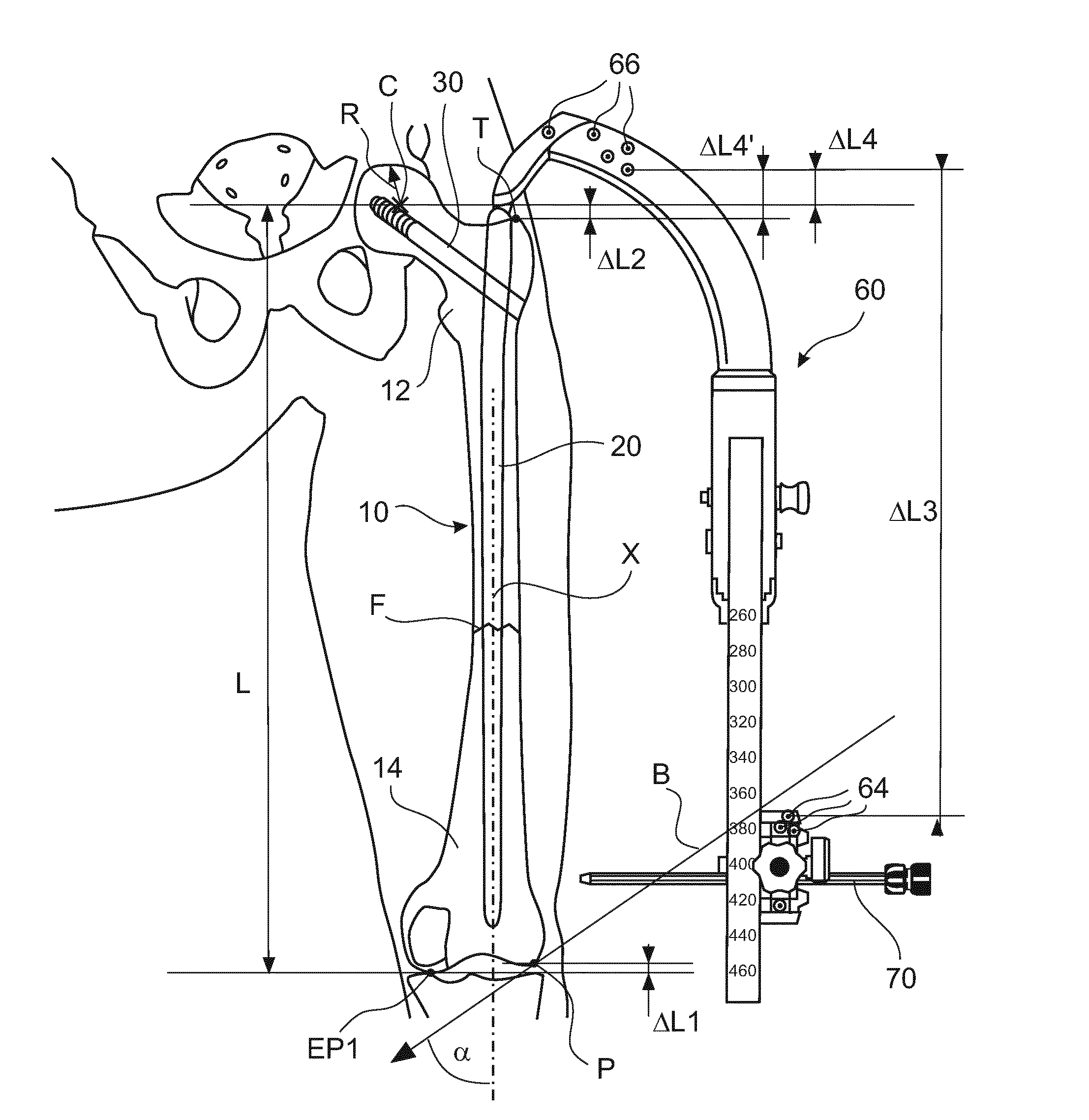
[0045]In accordance with one method, in step S11, a first image of a bone is received. The first image may be a fluoroscopic image of a proximal section of a long bone. For example, the image may be generated in a lateral to medial direction, i.e. substantially perpendicular to a longitudinal axis of the long bone. In step S12, a visible aspect or feature of the bone as well as elements of a first reference body 66 are detected in the received image. In step S13, a spatial position of a first point C, T at the bone is determined (ΔL4 or ΔL4′ in FIG. 3).

[0046]In step S21, a second image of the bone is received. The second image may ...


PUM


Abstract

A method and a device are provided, for measuring an actual length of a fractured bone based on 2D fluoroscopic images of proximal and distal sections of the bone, each of the images including a reference body. Based on the images, a spatial position of a first end point and a spatial position of a second end point are determined, taking into account dimensions taken from a bone model of a bone corresponding to the imaged bone and the spatial positions of the reference bodies. The actual length of the fractured bone is defined as the distance between the two end points.

Description

FIELD OF THE INVENTION[0001]The invention relates to the field of computer assisted surgery. In particular, the invention relates to a method and a device for determining an actual length of a fractured bone based on fluoroscopic images. The method may be implemented as a computer program executable on a processing unit of the device.BACKGROUND OF THE INVENTION[0002]In a case in which a shaft of a long bone is fractured, a bone nail may be used to stabilize the parts of the bone during the healing of the fracture, wherein the bone nail may be inserted into a medullary channel of the bone in a longitudinal direction thereof. However, such a bone nail may allow a shifting of one part of the bone relative to another part of the bone, along the axis of the bone nail, at least until a locking screw is inserted through the bone nail in a lateral direction to fix the position of the shiftable part.[0003]Accordingly, a physician should position the fractured parts as anatomically correct as...

Claims


Application Information

Patent Timeline
IPC IPC(8): A61B34/10A61B6/00A61B17/17
CPCA61B34/10A61B17/1703A61B17/1725A61B6/4441A61B6/505A61B6/5217A61B6/487A61B2034/108A61B2090/3966G16H50/30
Inventor BLAU, ARNOSIMON, BERNDMETZ, LARS
Owner STRYKER EURO OPERATIONS HLDG LLC
Why Eureka
Try Eureka