
Robotic device for dental surgery

a robotic device and dental surgery technology, applied in dental surgery, dental instruments, applications, etc., can solve the problems of increasing discomfort of patients having to have additional procedures performed, affecting the healing process of gingival cavities, and requiring expensive intraoral scanning equipmen

Active Publication Date: 2016-12-08
BIOMET 3I LLC
View PDF8 Cites 26 Cited by
  • Summary
  • Abstract
  • Description
  • Claims
  • Application Information

AI Technical Summary

Benefits of technology

The patent describes a robotic system for use during dental procedures, specifically the installation of dental implants. The system includes a base, a grounding arm, and a working arm. The grounding arm is attached to the patient's mouth to serve as the origin for the system, and the working arm is movable to perform the procedures. The system also includes sensors that monitor the position of the grounding arm and the working arm, providing data that is used to create a virtual model of the patient's mouth. The virtual model is useful for creating a post-operative virtual model of the mouth, which can help with dental implant procedures. The method described in the patent involves attaching a rigid grounding member to the patient's mouth, obtaining a pre-operative virtual model of the mouth, and then using the robotic system to install the dental implant. The system can also be used to shave bone in the mouth and prepare for the installation of the dental implant.

Problems solved by technology

The replacing of the heating abutment with the scanning abutment, even for a short period of time, has disadvantages, such as, added discomfort to the patient having to have additional procedures performed, disruption to the gingival healing process, etc.
While these systems do not require the removal of the healing abutment to create the virtual three-dimensional model, they still do require the intraoral scanning step, which requires expensive intraoral scanning equipment.

Method used


Image

  • Robotic device for dental surgery
  • Robotic device for dental surgery
  • Robotic device for dental surgery

Examples


Embodiment Construction

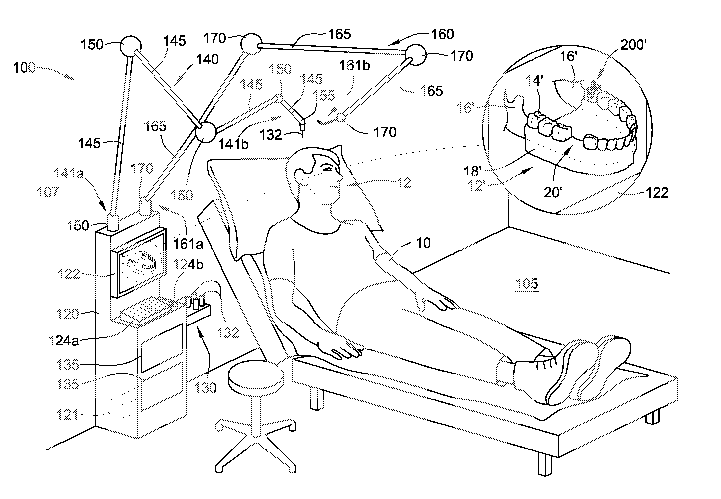
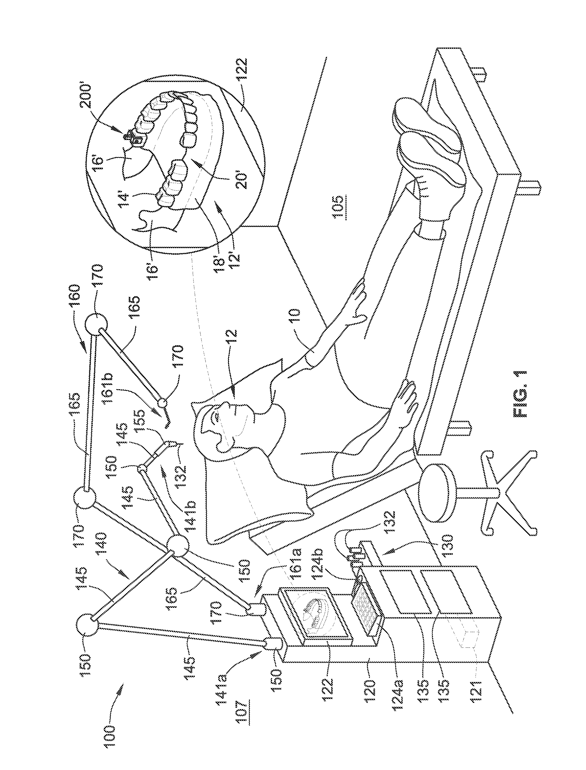
[0038]Referring to FIG. 1, a robotic system 100 of the present disclosure can be used in a variety of manners to perform a variety of surgical and / or non-surgical procedures. Once the robotic system 100 is registered to a patient 10 and loaded with a pre-determined surgical plan, the robotic system 100 is ready to automatically carry out one or more surgical procedures or portions thereof. By automatically, it is meant that the robotic system can, without interruption or input from a human (e.g., other than registering the robotic system 100, loading the pre-determined surgical plan, and in some implementations hitting a start button), perform a surgical procedure or portion thereof.

[0039]Additionally, the robotic system 100 can be manually manipulated by, for example, an oral surgeon to be used in performing one or more surgical procedures. Manually performing a surgical procedure using the robotic system 100 aids the surgeon as compared to performing a manually procedure without t...


PUM


Abstract

A robotic system includes a base, a grounding arm, a working arm, and one or more sensors. The grounding arm extends from the base and is configured to be coupled to a fixed structure within the mouth of the patient for establishing an origin for the robotic system. The working arm extends from the base and is configured to be coupled with one or more tools for use during an installation of a dental implant in the mouth. The one or more sensors are for monitoring positions of the grounding arm and / or the working arm and to generate positional data that is used to create a post-operative virtual three-dimensional model of at least a portion of the mouth of the patient.

Description

CROSS-REFERENCE TO RELATED APPLICATIONS[0001]This application claims the benefit of U.S. Provisional Patent Application Ser. No. 62 / 170,038, filed on Jun. 2, 2015, the benefit of priority of which is claimed hereby, and which is incorporated by reference herein in its entirety.FIELD OF THE INVENTION[0002]The present disclosure relates generally to robotic systems and methods of using the same. More particularly, the present disclosure relates to using a robotic system to (i) automatically perform a variety of dental procedures and / or (ii) monitor a manually performed dental procedure, thereby generating positional data of the robotic system that is usable in creating a modified three-dimensional model for use in developing a final and / or temporary dental prosthesis (e.g., crown, abutment, etc.).BACKGROUND OF THE INVENTION[0003]The dental restoration of a partially or wholly edentulous patient with artificial dentition typically begins with an incision being made through the patient'...

Claims


Application Information

Patent Timeline
IPC IPC(8): A61B34/32A61B34/20A61B17/3211A61C8/00
CPCA61B34/32A61C8/0089A61B2034/105A61B17/3211A61B2034/102A61B34/20A61B34/30A61C1/082A61B2034/2059A61B2090/3991A61B2090/3983A61B2090/363
Inventor SUTTIN, ZACHARY B.PORTER, STEPHEN S.
Owner BIOMET 3I LLC
Learn More