Inhalator and inhalator set

Active Publication Date: 2016-12-08
PARI PHARMA GMBH
View PDF6 Cites 20 Cited by
  • Summary
  • Abstract
  • Description
  • Claims
  • Application Information

AI Technical Summary

Benefits of technology

[0007]In view of the aforesaid, it is one object of the present invention to provide an inhalator that is more stable when suppo

Problems solved by technology

However, also non-pharmaceutical solutions such as saline solutions may be used.
Even though this kind of connection has proven beneficial in many regards, the use of a cable is under certain circumstances considered inconvenient for the user.
Thus, if the inhalator is supported on the horizontal surface during non-use, the inhalator tends to tilt with the risk of dropping and damaging the inhalator.
Furthermore, either one of the above configurations have proven not very ergonomic during inhalation.
The on

Method used


Image

  • Inhalator and inhalator set
  • Inhalator and inhalator set
  • Inhalator and inhalator set

Examples


Embodiment Construction

[0054]In the drawings, the same elements have been designated by the same reference numerals.

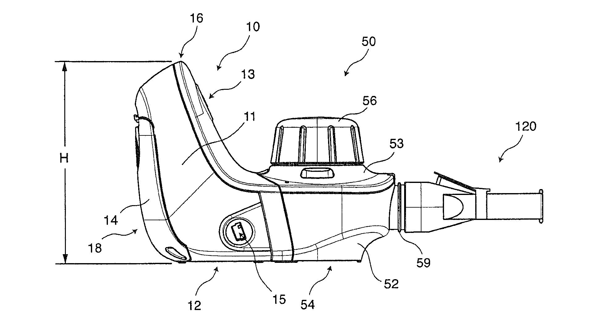
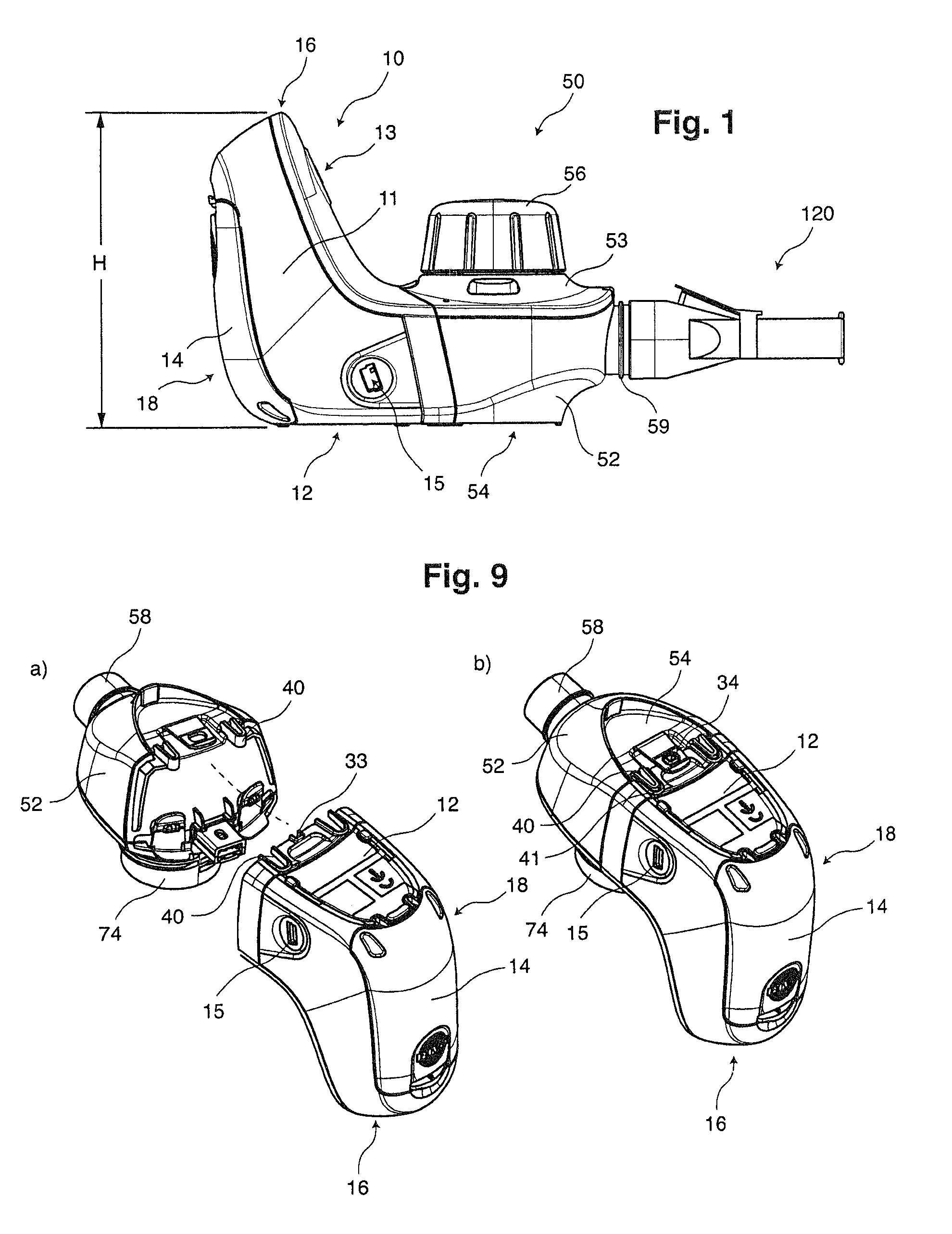
[0055]The inhalator as shown in FIG. 1 comprises a controller unit 10 and an aerosol generator unit 50 which are connected to each other. Further, a mouthpiece 120 is provided.

[0056]The controller unit 10 has a housing (the first housing) 11. The housing has at its lower end a base 12 for supporting the inhalator on a horizontal surface such as a desk. Integrated into the housing 11 is an ON / OFF button 13 and a battery compartment lid 14 that is removable from the housing 11 for exchanging batteries. A USB socket 15 is provided at one side of the housing 11, which may be used for connection to a power supply and / or charging the batteries in the battery compartment and / or for connection of the inhalator to a personal computer.

[0057]A top 16 is defined opposite to the base 12, wherein the total height H of the inhalator is defined between the base 12 and the top 16. The height H of the inhalat...


PUM


Abstract

Inhalator (50) comprising an aerosol generator (64) configured to generate an aerosol by nebulizing a fluid and a controller (24) configured to control operation of the aerosol generator and a housing (11, 51) accommodating at least the aerosol generator and the controller, the housing having a base (12) for supporting the housing on a horizontal surface, wherein a portion (35) of the housing accommodating at least a portion of the controller is arranged further away from the base than the aerosol generator as seen in a vertical direction, when the base is supported on the horizontal surface.

Description

TECHNICAL FIELD[0001]The present invention relates to an inhalator and an inhalator set. In particular, the present invention relates to inhalators that are configured to nebulize a fluid for producing an aerosol to be inhaled by an individual. In general, the aerosol will contain an active ingredient, particularly a pharmaceutical ingredient for therapeutic purposes. However, also non-pharmaceutical solutions such as saline solutions may be used.BACKGROUND[0002]Such inhalators are generally configured of an aerosol generator unit and a controller unit containing the controller for controlling operation of the aerosol generator as part of the aerosol generator unit. In principle, there are two concepts for connecting the controller unit and the aerosol generator unit known in the art. One concept suggests to accommodate each unit in separate housings and electrically connect the controller and the aerosol generator by use of a relatively long (e.g. 1 m) cable. Such inhalators are fo...

Claims


Application Information

Patent Timeline
IPC IPC(8): A61M11/00A61M16/06A61M16/04A61M15/00
CPCA61M11/00A61M15/0021A61M16/06A61M2205/8206A61M2205/50A61M2205/586A61M2209/10A61M16/04A61M11/005A61M15/0085A61M15/0015A61M2205/35A61M2205/581A61M2209/06A61M2016/0015B05B17/0646
Inventor MCPHERSON ALLNUTT, TOMACHTZEHNER, WOLFGANGGALLEM, THOMASHETZER, UWE
Owner PARI PHARMA GMBH
Why Eureka
Try Eureka