
Self-monitoring of vehicles in a convoy

a vehicle and convoy technology, applied in the field of vehicle control, can solve the problems of remote roadways traversing a number of hazards, inconvenient air freight, and lack of safety features on the roads used for accessing such locations

Inactive Publication Date: 2016-12-15
AWARE 360
View PDF8 Cites 43 Cited by
  • Summary
  • Abstract
  • Description
  • Claims
  • Application Information

AI Technical Summary

Benefits of technology

The present invention relates to a method and device for maintaining the speed and distance between vehicles in a convoy. The method involves determining the locations and speeds of the vehicles, transmitting this information to other vehicles in the convoy, and providing auditory and / or visual alerts to the driver of the individual vehicle if they violate the speed or distance limits set for the convoy route. The device includes a satellite positioning receiver, a radio modem, and databases containing map data, speed limits, and vehicle distance limits. The method and device can help to maintain safe driving habits and improve operational efficiency for convoy vehicles.

Problems solved by technology

Efforts to transport supplies to remote communities or industrial sites at remote locations have a number of logistical problems.
One such problem is that the roadways used for access to such locations are not provided with safety features common to major roadways servicing populated areas due to prohibitive costs associated therewith.
In addition, remote roadways tend to traverse a number of hazards.
The use of ice roads reduces the cost of materials that otherwise would be shipped as expensive air freight, and they allow movement of large or heavy objects for which air freight is impractical.
As such, the transport of goods and supplies across ice roads will involve a number of topographical hazards.

Method used


Image

  • Self-monitoring of vehicles in a convoy
  • Self-monitoring of vehicles in a convoy
  • Self-monitoring of vehicles in a convoy

Examples


example 1

Self-Monitoring of Transport Vehicles on an Ice Road Route

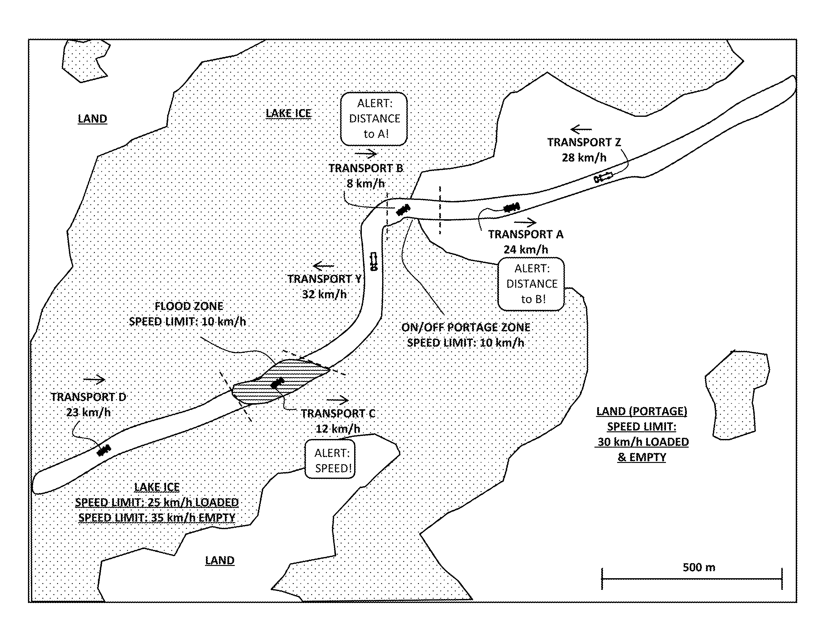
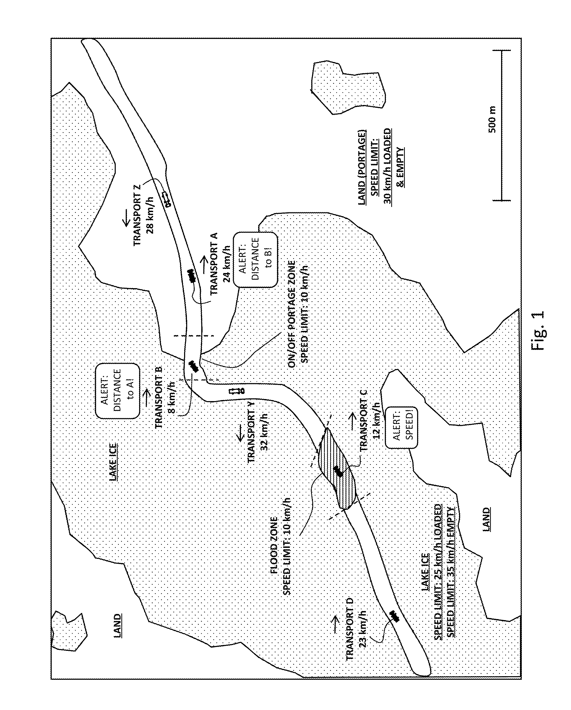
[0068]This example illustrates how the self-monitoring process operates for transport vehicles in a convoy on an ice road route. The section of the route shown in FIG. 1 has five different segments with differing speed limits as indicated in Table 2 below.

TABLE 2Ice Road Route Speed and Distance LimitsSpeedDistanceDescription of Roadway Segment andLimitLimit (m)Transport Condition(km / h)(min / max)Lake Surface: Loaded Vehicle25500 / 1000Lake Surface: Empty Vehicle35500 / 1000Portage: Loaded or Empty Vehicle30500 / 1000Flood Zone on Lake10500 / 1000On / Off Portage Zone10500 / 1000

[0069]A first convoy with four vehicles shown (Transports A to D) is moving on the roadway from left to right and a second convoy with two vehicles shown (Transports Y and Z) is moving from right to left. The first convoy includes loaded transports and the second convoy includes empty transports.

[0070]Transport A is traveling on a portage zone at a speed of 24 km / h...

example 2

Self-Monitoring of Six Vehicles in a Convoy Traveling on Land

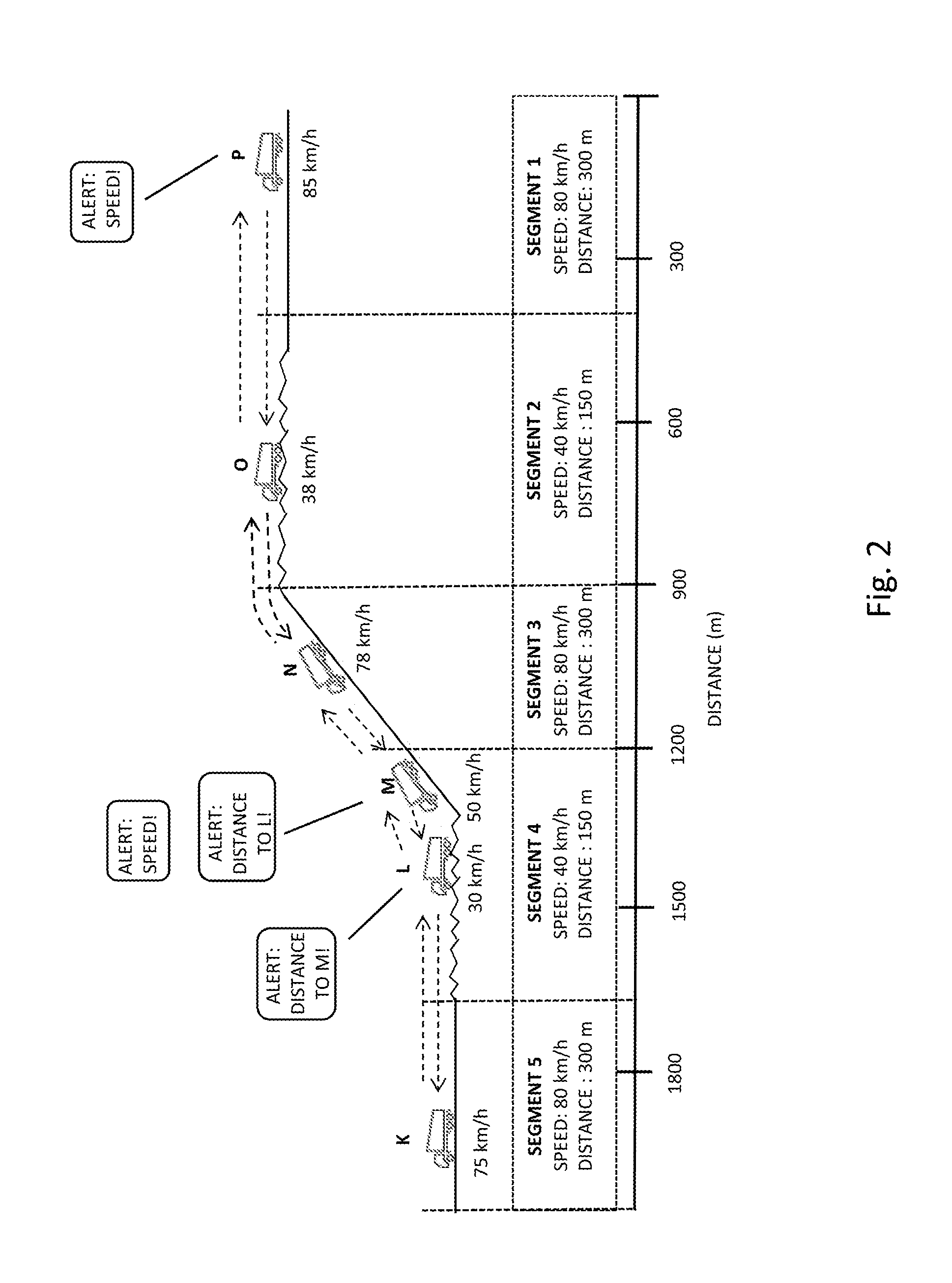
[0075]Although a number of features of the invention have been described in context of convoy vehicles traveling on an ice road, the invention may also be used for other convoy applications other than ice road transport. FIG. 2 is a diagram showing a fleet of six transport vehicles (Transports K to P) in a convoy which is spread out over five segments of a roadway on land with various topographical and surface features. The speed and distance considerations relate to potential dangers resulting from topography and surface conditions.

[0076]Segment 1, on the right side of FIG. 2 has a flat smooth surface and has been assigned a speed limit of 80 km / h and a spacing limit (distance) between vehicles of 300 m.

[0077]Segment 2, to the immediate left of Segment 1 has a flat rough surface and has been assigned a speed limit of 40 km / h and a spacing limit between vehicles of 150 m.

[0078]Segment 3, to the immediate left of Segment 2 ...

example 3

Operation of One Embodiment of the Network Device

[0087]One embodiment of a network device for receiving convoy data and providing alerts to a driver of a vehicle will now be described with reference to FIG. 3 where the flow of data into the network device 10 is shown with dashed-line arrows, the flow of data within the device is shown with solid arrows and the flow of data out of the device is shown with dot-dashed arrows. This embodiment will be described with reference to an example convoy wherein each vehicle of the convoy includes a substantially similar network device having substantially similar functional capabilities. The skilled person will recognize that in such a situation, there is no “master-slave” arrangement or no “control vehicle” directing the convoy. Alerts are issued to a given vehicle based on its own speed data as well as its position data and the position data of leading and trailing vehicles. If the given vehicle is the first vehicle of the convoy, it will rec...


PUM


Abstract

A method for maintaining vehicle speeds and distances between vehicles travelling in a convoy along a convoy route. The method includes determining locations and speeds of the vehicles; transmitting the locations and speeds of the vehicles by radio transmission to any of the other vehicles of the convoy within radio communication range; providing an automated speed alert to a driver of an individual vehicle of the vehicles if the speed of the individual vehicle violates a speed limit for a segment of the convoy route; and providing an automated distance alert to the driver of the individual vehicle if the individual vehicle violates a distance limit for a segment of the convoy route with respect to leading and / or trailing vehicles of the fleet of vehicles.

Description

CROSS REFERENCE TO RELATED APPLICATIONS[0001]This application claims priority from U.S. Provisional Application Ser. No. 62 / 172,873 filed Jun. 9, 2015, which is incorporated herein by reference in its entirety.FIELD OF THE INVENTION[0002]The invention relates to the field of vehicle control and provides methods and systems for this purpose.BACKGROUND OF THE INVENTION[0003]Efforts to transport supplies to remote communities or industrial sites at remote locations have a number of logistical problems. One such problem is that the roadways used for access to such locations are not provided with safety features common to major roadways servicing populated areas due to prohibitive costs associated therewith. In addition, remote roadways tend to traverse a number of hazards.[0004]One such example of a remote roadway is an ice road. Ice roads are frozen pathways on the surface of bays, rivers, lakes, or seas in polar regions. They link dry land, frozen waterways, portages and winter roads,...

Claims


Application Information

Patent Timeline
IPC IPC(8): B60Q9/00G01C21/34G08G1/01G01S19/42G08G1/052G08G1/00
CPCB60Q9/00G08G1/052G01C21/34G08G1/0145G01S19/42G08G1/22G01S19/14G01S5/0072B60K31/18B60W50/14G08G1/096716G08G1/096741G08G1/096775G08G1/163B60W2050/143B60W30/16B60W2520/10B60W2050/146B60W2556/65B60W2555/60B60W2554/801B60W2556/50
Inventor MATTHEWS, STEVEN GREGORYMCLELLAN, JAMES FREDERICK
Owner AWARE 360
Learn More