Piezoelectric driving device for motor, motor, robot, and pump
a driving device and piezoelectric technology, applied in the direction of machines/engines, generators/motors, positive displacement liquid engines, etc., can solve the problems of low force for pressing the vibrating plate, damage to the vibrating plate, and inability to increase the output, etc., to achieve high output
- Summary
- Abstract
- Description
- Claims
- Application Information
AI Technical Summary
Benefits of technology
Problems solved by technology
Method used
Image

Examples
first embodiment
1. First Embodiment
1.1. Piezoelectric Driving Device for Motor
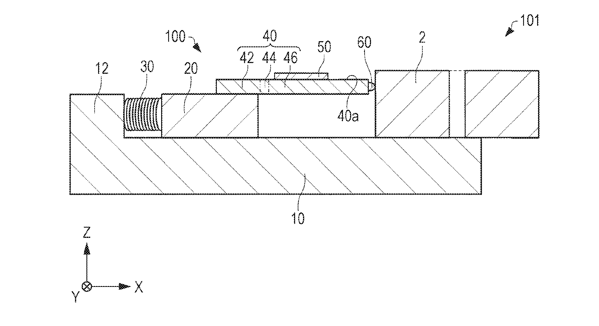
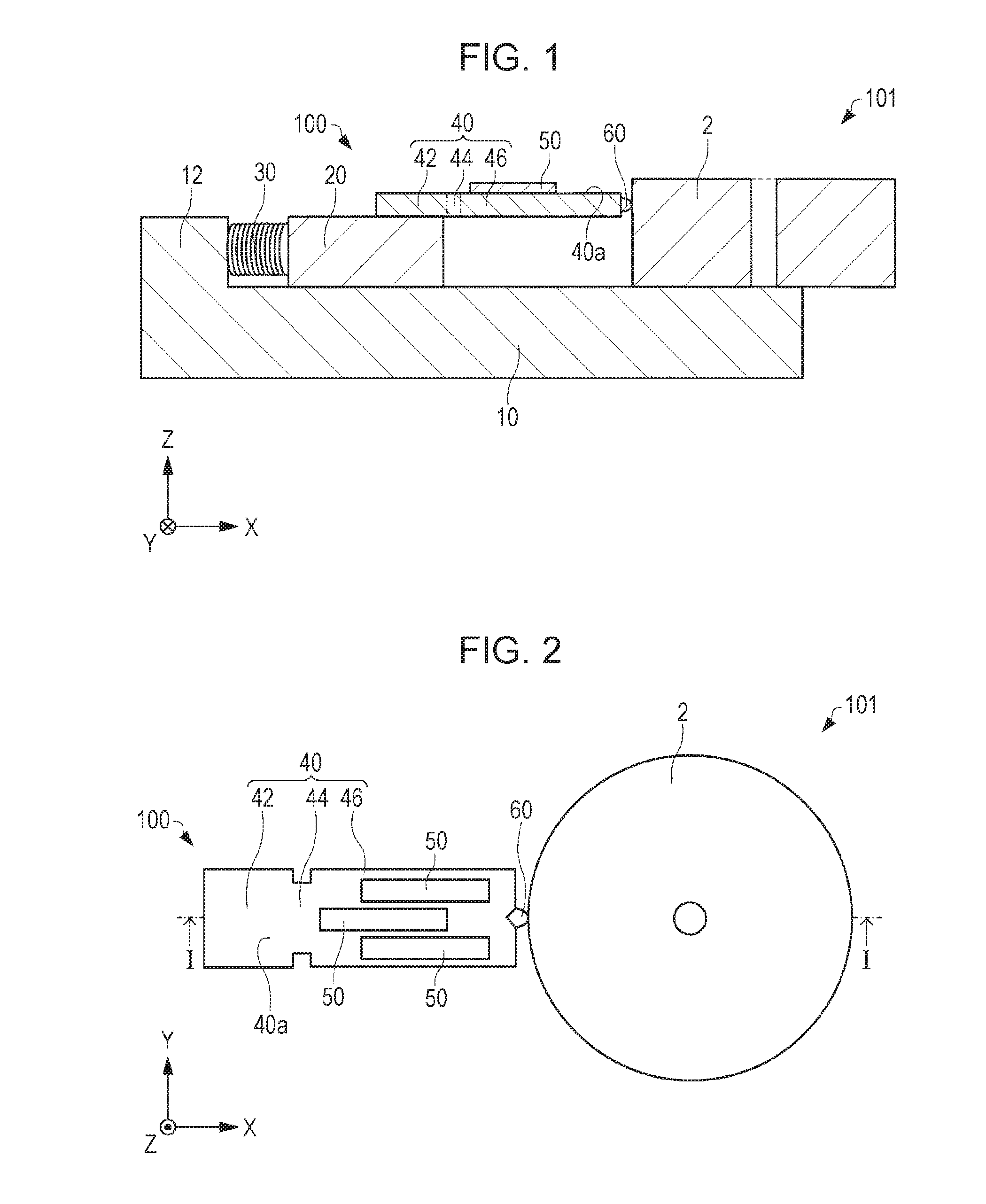
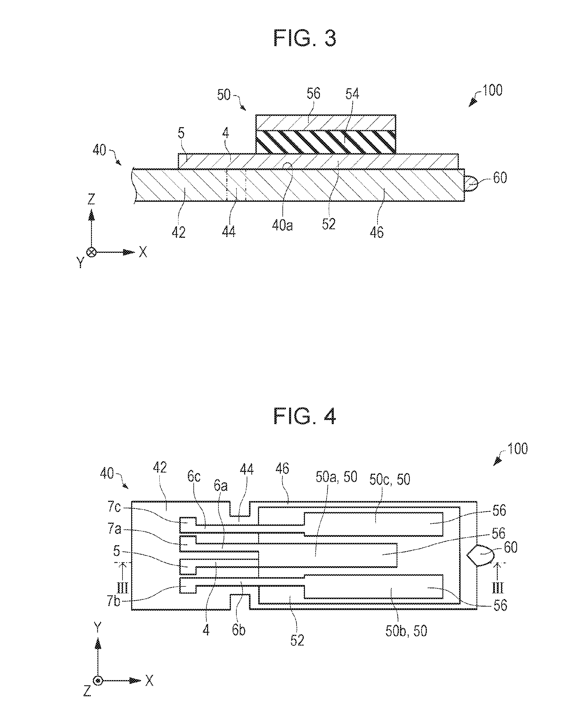
[0081]First, a piezoelectric driving device for a motor according to a first embodiment will be described with reference to the drawings. FIG. 1 is a sectional view schematically showing a piezoelectric driving device for a motor 100 according to the first embodiment. FIG. 2 is a plan view schematically showing the piezoelectric driving device for a motor 100 according to the first embodiment. FIG. 1 is a sectional view taken along a line I-I of FIG. 2. FIGS. 1, 2, and 3 to 8 and 10 which will be described later show an X axis, a Y axis, and a Z axis orthogonal to each other.
[0082]As shown in FIG. 1 and FIG. 2, the piezoelectric driving device for a motor 100 includes a substrate 10, a fixed plate 20, a spring 30, a vibrating plate 40, a piezoelectric element 50, and a contact portion (protrusion) 60. The piezoelectric driving device for a motor 100 and a rotor (driven body) 2 configure a motor 101. The rotor 2 is rotated...
second embodiment
2. Second Embodiment
2.1. Piezoelectric Driving Device for Motor
[0141]Next, a piezoelectric driving device for a motor according to a second embodiment will be described with reference to the drawings. FIG. 11 is a plan view schematically showing a piezoelectric driving device for a motor 300 according to the second embodiment. FIG. 12 is a sectional view taken along a line XII-XII of FIG. 11 schematically showing the piezoelectric driving device for a motor 300 according to the second embodiment. FIGS. 11 and 12, and FIGS. 13 to 18B, 23, and 31 which will be described later show an X axis, a Y axis, and a Z axis orthogonal to each other. For convenience, in FIG. 11, the substrate 10, the fixation member 20, and the spring 30 are not shown. In FIG. 11 and FIG. 12, the piezoelectric element 50 is simplified.
[0142]Hereinafter, in the piezoelectric driving device for a motor 300 according to the second embodiment, the same reference numerals are used for members having the same function...
first modification example
2.3.1 First Modification Example
[0158]Next, a piezoelectric driving device for a motor according to a first modification example of the second embodiment will be described with reference to the drawings. FIG. 13 is a plan view schematically showing a piezoelectric driving device for a motor 400 according to a first modification example of the second embodiment. In FIG. 13, the substrate 10, the fixation member 20, the spring 30, the wirings 4, 6a, 6b, and 6c, and the terminals 5, 7a, 7b, and 7c are not shown and the piezoelectric element 50 is simplified.
[0159]Hereinafter, in the piezoelectric driving device for a motor 400 according to a first modification example of the second embodiment, the same reference numerals are used for members having the same functions as constituent elements of the piezoelectric driving device for a motor 300 according to the second embodiment and the specific description thereof will be omitted. The same applies to a piezoelectric driving devices for a...
PUM
 Abstract
Description
Claims
Application Information
 - R&D
- Intellectual Property
- Life Sciences
- Materials
- Tech Scout
- Unparalleled Data Quality
- Higher Quality Content
- 60% Fewer Hallucinations
Browse by: Latest US Patents, China's latest patents, Technical Efficacy Thesaurus, Application Domain, Technology Topic, Popular Technical Reports.
© 2025 PatSnap. All rights reserved.Legal|Privacy policy|Modern Slavery Act Transparency Statement|Sitemap|About US| Contact US: help@patsnap.com