Method for estimating petrophysical properties of a hydrocarbon reservoir

a hydrocarbon reservoir and hydrocarbon technology, applied in the field of hydrocarbon reservoir characterization, can solve the problems of uncertainty, lack of direct, and insufficient collection of core samples

Inactive Publication Date: 2016-12-22
SCHLUMBERGER TECH CORP
View PDF4 Cites 14 Cited by
  • Summary
  • Abstract
  • Description
  • Claims
  • Application Information

AI Technical Summary

Benefits of technology

[0017]The 3D porous solid images may contain information about 3D wettability and / or mineral distribution acquired by distribution of properties captured by 2D imaging techniques to the 3D X-ray microCT image.

Problems solved by technology

A lot of uncertainties arise due to the indirect nature of measurements, large errors in applied correlations, possibly inadequate collection of core samples or / and lack of direct petrophysical information in respect to the considered formation.

Method used


Image

  • Method for estimating petrophysical properties of a hydrocarbon reservoir
  • Method for estimating petrophysical properties of a hydrocarbon reservoir
  • Method for estimating petrophysical properties of a hydrocarbon reservoir

Examples


Embodiment Construction

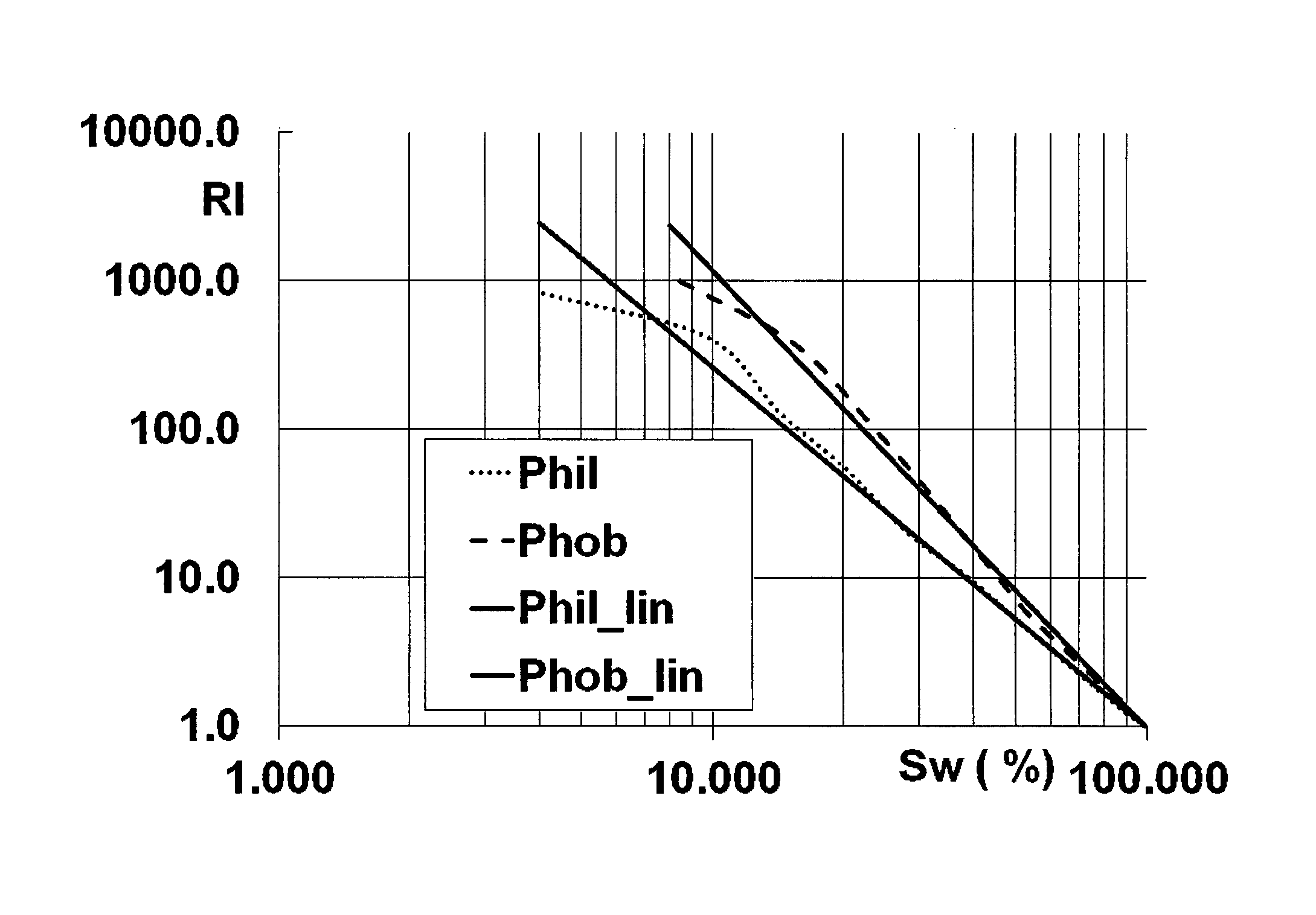
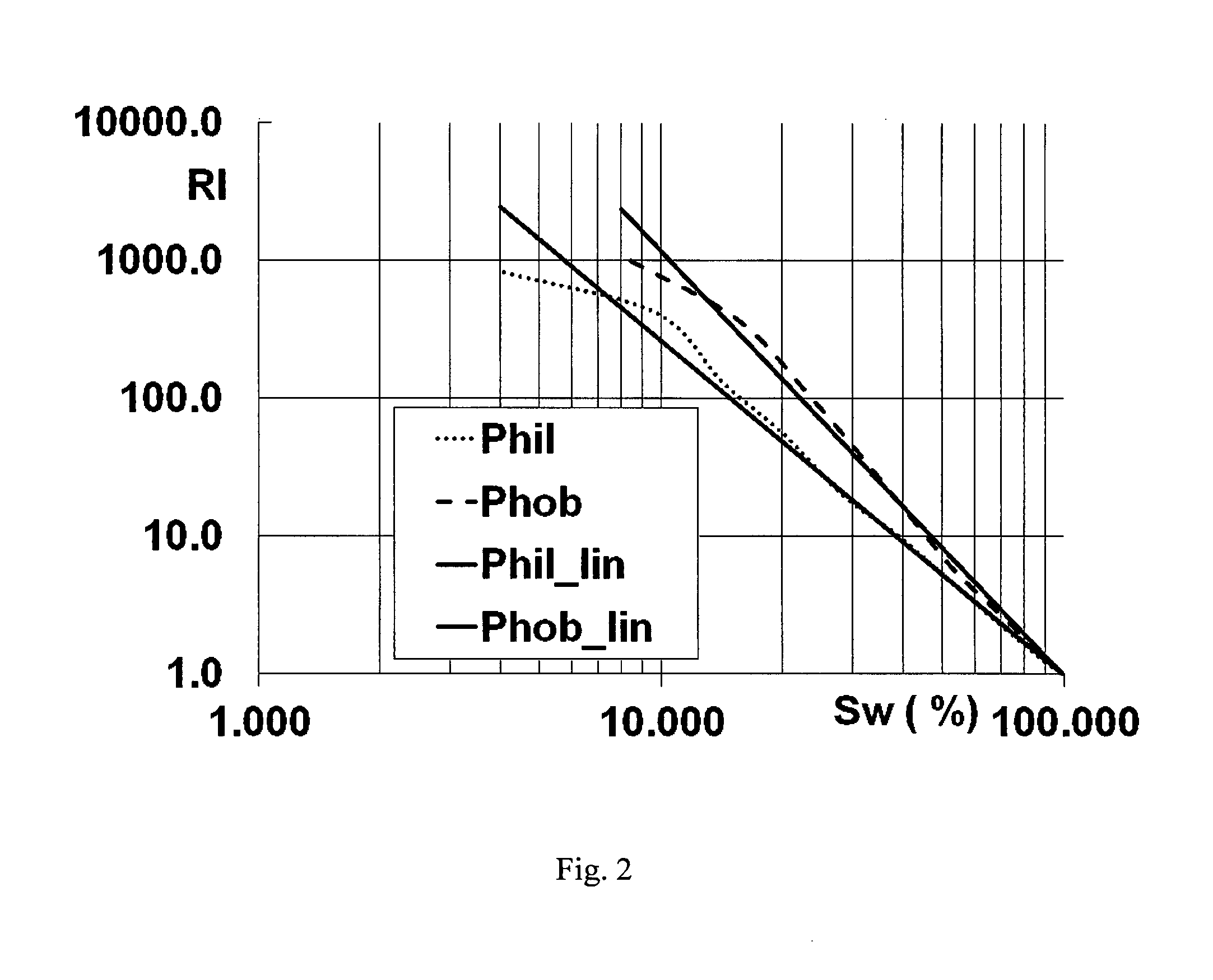
[0019]A detailed description is provided for one embodiment of the invention, which demonstrates typical steps of our workflow in case of interpretation of well resistivity measurements in terms of water saturation distribution for the oil reservoir.

[0020]A core sample with typical petrophysical properties is obtained from a wellbore traversing a hydrocarbon reservoir. The core sample may be obtained by drilling at a selected depth and extracting a core sample.

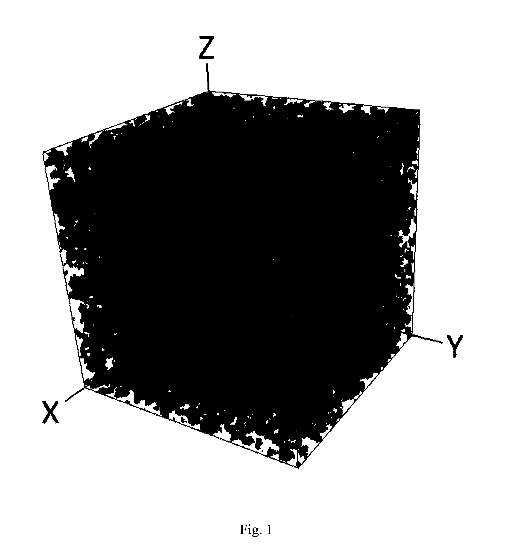
[0021]A 3D porous solid image of the core sample is obtained by scanning the core sample. A 3D porous solid image is a 3D digital representation of the core sample. Specifically, the 3D porous solid image is an image of each portion of the core sample including pores and solid surfaces. Thus, the 3D porous solid image may show pores and rock boundaries of the core sample for each layer of the core sample. Obtaining the 3D porous solid image may be accomplished by scanning the core sample. For example, X-ray micro tomography, 3...


PUM

PropertyMeasurementUnit
cell sizeaaaaaaaaaa
3D pore scale modelaaaaaaaaaa
pore structureaaaaaaaaaa

Abstract

Estimating petrophysical properties of a hydrocarbon reservoir traversed by at least one wellbore comprises obtaining at least one core sample from the wellbore and obtaining a three-dimensional (3D) porous solid image of the core sample. A 3D pore scale model is generated from the 3D porous solid image. A distribution of reservoir fluids in pores of the reservoir is simulated by a microhydrodynamic simulation using the 3D pore scale models of the core samples and at least one petrophysical property of the reservoir by a microscale modeling using the simulated distribution of the reservoir fluids is simulated by fitting the at least one simulated petrophysical property to well logging data at a depth corresponding to a depth of taking the core sample using free parameters. Governing parameters of the 3D pore scale models are extrapolated along a logged part of the wellbore and the at least one other petrophysical property is estimated by simulation.

Description

FIELD OF THE INVENTION[0001]This invention relates generally to a method of characterizing hydrocarbon reservoirs, namely to estimating properties of a formation by well logging interpretation.BACKGROUND[0002]At present all well logging techniques allow only indirect characterization of the natural reservoirs of fluid hydrocarbons. This means that any particular well logging method provides measurements of certain formation physical property (resistivity, spontaneous polarization, acoustic velocity, NMR response, etc.), which can be related to reservoir characterization (rock type, porosity, saturation, permeability) through experimental or theoretical correlations (like Archie's correlation between resistivity and porosity, see, for example, Bateman R. M. Open-hole Log Analysis and Formation Evaluation. Boston: IHRDC Publ., 1985, Tittman J. Geophysical Well Logging. Orlando (Florida): Academic Press, 1986, Bassiouni Z. Theory, Measurement, and Interpretation of Well Logs. Richardso...

Claims


Application Information

Patent Timeline
Patent Type & Authority Applications(United States)
IPC IPC(8): E21B41/00G01V99/00G01N15/08E21B49/00
CPCE21B41/0092G01N15/088G01V99/005E21B49/00G01V5/08G01N2015/0846E21B41/00G06F30/28
Inventor SAFONOV, SERGEY SERGEEVICHDINARIEV, OLEG YURYEVICHEVSEEV, NIKOLAY VYACHESLAVOVICHDEMIANOV, ALEXANDER YURYEVICHKOROTEEV, DMITRY ANATOLIEVICH
Owner SCHLUMBERGER TECH CORP
Why Eureka
Try Eureka