Heat source side unit and refrigeration cycle apparatus

a technology of side units and heat sources, applied in the direction of indirect heat exchangers, lighting and heating apparatus, refrigeration components, etc., can solve the problems of impaired comfortability and more likely to be frosted, and achieve the effect of efficient defrosting of heat source side heat exchangers, high accuracy, and rapid restoration of defrosted outdoor side heat exchangers

Active Publication Date: 2016-12-22
MITSUBISHI ELECTRIC CORP
View PDF1 Cites 22 Cited by
  • Summary
  • Abstract
  • Description
  • Claims
  • Application Information

AI Technical Summary

Benefits of technology

[0016]According to the present invention, it is possible to efficiently defrost a heat source side heat exchanger to be defrosted, while keeping heating of a load like heating of a space to be air-conditioned. Further, it is possible to determine completion of defrosting with high accuracy, and to restore a defrosted outdoor side heat exchanger as an evaporator quickly.

Problems solved by technology

On the other hand, however, in a heat pump type air-conditioning apparatus, when the temperature of the air outside the room (outside air) (outside air temperature) is decreasing, an outdoor heat exchanger, functioning as an evaporator to allow heat exchange between the outside air and refrigerant, is more likely to be frosted.
However, in this method, as defrosting is performed while stopping heating in the room in some cases, there is a problem that comfortability is impaired.

Method used


Image

  • Heat source side unit and refrigeration cycle apparatus
  • Heat source side unit and refrigeration cycle apparatus
  • Heat source side unit and refrigeration cycle apparatus

Examples


embodiment 1

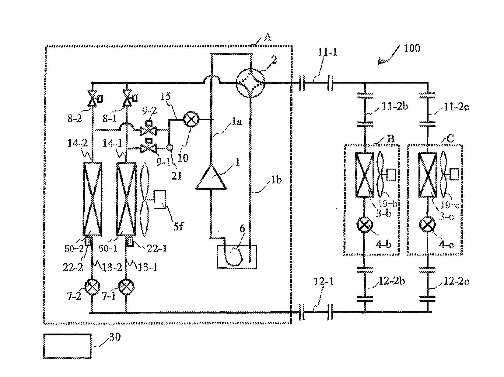
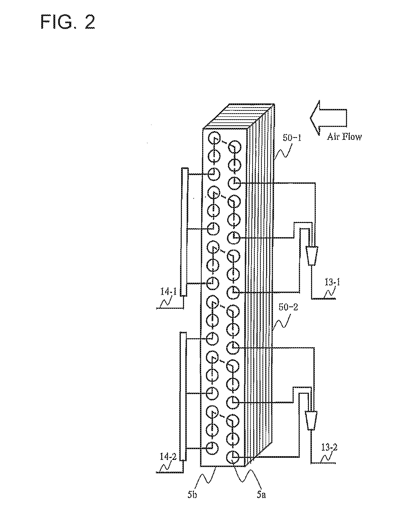
[0040]FIG. 1 is a diagram showing a configuration of an air-conditioning apparatus 100 having a heat source side unit according to Embodiment 1 of the present invention. The air-conditioning apparatus 100 of Embodiment 1 includes an outdoor unit A serving as a heat source side unit, and a plurality of indoor units (use side units) B and C connected in parallel with each other. The outdoor unit A and the indoor units B and C are connected via first extension pipes 11-1 and 11-2b and 11-2c, and second extension pipes 12-1 and 12-2b and 12-2c, which constitute a refrigerant circuit. The air-conditioning apparatus 100 also includes a controller 30. The controller 30 controls a cooling operation or a heating operation (a heating normal operation or a heating defrosting operation) of the indoor units B and C. In this example, the controller 30 of Embodiment 1 is configured of a microcomputer or another device having a control arithmetic processing unit such as a Central Processing Unit (C...

embodiment 2

[0124]FIG. 21 is a diagram showing a configuration of an air-conditioning apparatus 100 according to Embodiment 2 of the present invention. In FIG. 21, devices and the like denoted by the same reference numerals or characters perform operations similar to that described in Embodiment 1. Hereinafter, description will be given mainly on the aspects of an air-conditioning apparatus 100 of Embodiment 2 that are different from the aspects of the air-conditioning apparatus 100 of Embodiment 1.

[0125]In the air-conditioning apparatus 100 according to Embodiment 2, a compressor 1 includes an injection port from which refrigerant can be introduced (injected) from the outside of the compressor 1 to a compression chamber for compressing the refrigerant in the compressor 1.

[0126]Further, an outdoor unit A of the air-conditioning apparatus 100 of Embodiment 2 includes a second defrosting pipe 16 for injecting refrigerant, having passed through the parallel heat exchanger 50 to be defrosted, into ...

embodiment 3

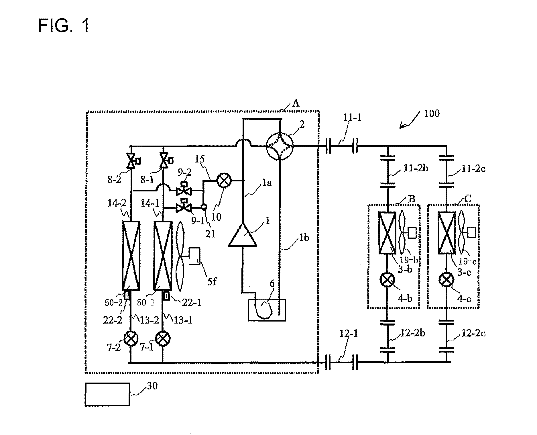
[0132]In Embodiment 1 and Embodiment 2 described above, description has been given on exemplary configurations in which the outdoor heat exchanger 5 is divided into a plurality of parallel heat exchangers 50-1 and 50-2. However, the present invention is not limited to this configuration. For example, a configuration having a plurality of independent outdoor heat exchangers 5, connected in parallel with each other, may be acceptable. It is possible to perform the heating defrosting operation in which a part of the outdoor heat exchanger 5 is set to be a target of defrosting and the rest of the outdoor heat exchanger 5 continues the heating operation.


PUM


Abstract

An outdoor unit, connected with indoor units by pipes to constitute a refrigerant circuit, includes a compressor configured to compress and discharge refrigerant, a plurality of parallel heat exchangers configured to allow heat exchange between air and the refrigerant, a first defrosting pipe serving as a flow path for branching a part of the refrigerant discharged by the compressor and allowing the refrigerant to flow into the parallel heat exchanger to be defrosted for defrosting, a first expansion device configured to decompress the refrigerant passing through the first defrosting pipe, a second expansion device configured to adjust the pressure of the refrigerant that passed through the parallel heat exchanger to be defrosted, and a controller configured to control the second expansion device such that the pressure of the refrigerant that passed through the parallel heat exchanger to be defrosted falls within a predetermined range.

Description

TECHNICAL FIELD[0001]The present invention relates to a heat source side unit and other units in a refrigeration cycle apparatus such as an air-conditioning apparatus.BACKGROUND ART[0002]In recent years, from a viewpoint of global environmental protection, cases of introducing heat pump type air-conditioning apparatuses, using the air as a heat source, are increasing even in cold areas, in place of boiler type heating devices in which heating is performed by burning fossil fuel. In a heat pump type air-conditioning apparatus, heating can be performed more efficiently by the amount of heat supplied from the air in addition to the electricity input to the compressor.[0003]On the other hand, however, in a heat pump type air-conditioning apparatus, when the temperature of the air outside the room (outside air) (outside air temperature) is decreasing, an outdoor heat exchanger, functioning as an evaporator to allow heat exchange between the outside air and refrigerant, is more likely to ...

Claims


Application Information

Patent Timeline
Patent Type & Authority Applications(United States)
IPC IPC(8): F25B47/02F28D1/04F25B13/00
CPCF25B47/022F25B13/00F28D1/0443F25B2313/0233F25B2313/0251F25B2313/0315F25B2341/0661F25B2600/2513F25B2313/0253F25B47/02F25B41/385
Inventor TAKENAKA, NAOFUMIWAKAMOTO, SHINICIWATANABE, KAZUYAYAMASHITA, KOJIHATOMURA, TAKESHI
Owner MITSUBISHI ELECTRIC CORP
Why Eureka
Try Eureka