Multiphase Thermal Flowmeter for Stratified Flow

a multi-phase thermal flowmeter and stratified flow technology, applied in the direction of survey, instruments, borehole/well accessories, etc., can solve the problem of interfering or temporarily halting fluid production

Active Publication Date: 2016-12-29
BAKER HUGHES INC
View PDF2 Cites 3 Cited by
  • Summary
  • Abstract
  • Description
  • Claims
  • Application Information

AI Technical Summary

Benefits of technology

[0005]Another example of a method of evaluating flow of a fluid downhole includes applying thermal energy to the flow of fluid at a position in the flow of fluid, sensing a temperature of the fluid stream downstream of the position over time at a first downstream location, sensing a temperature of the fluid stream downstream of the position over time at a second downstream location that is downstream of the first downstream location, and estimating a type of fluid in the (low of fluid based on a comparison of temperature profiles obtained by sensing temperatures at the first and second downstream locations. In one example, the method further includes estimating fluid flow based on a measurement of a time lapse between when the thermal energy is applied to the fluid, and when a peak of temperature is observed at the first downstream location, the method also optionally further involves repeating the steps of applying thermal energy and sensing temperature of the fluid stream al radial positions in the flow of fluid. The method optionally further includes identifying different phases of fluid within the flow of fluid.
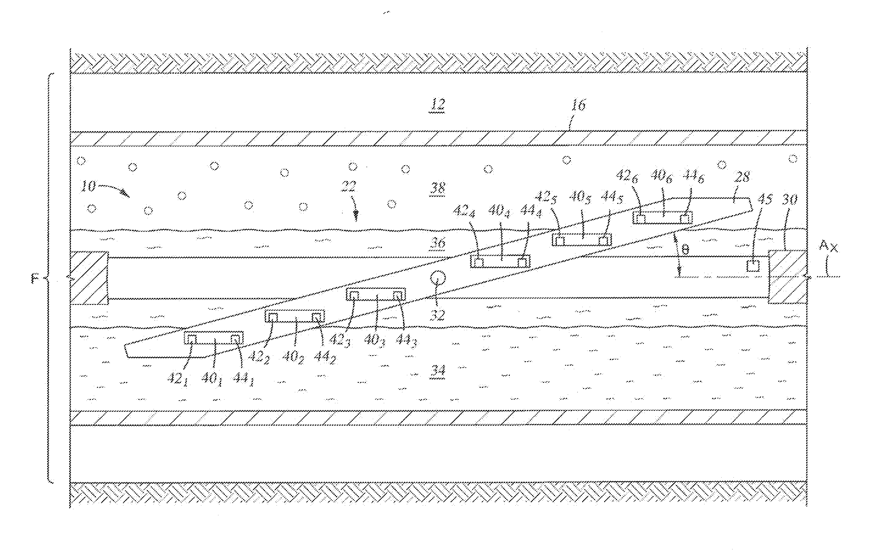
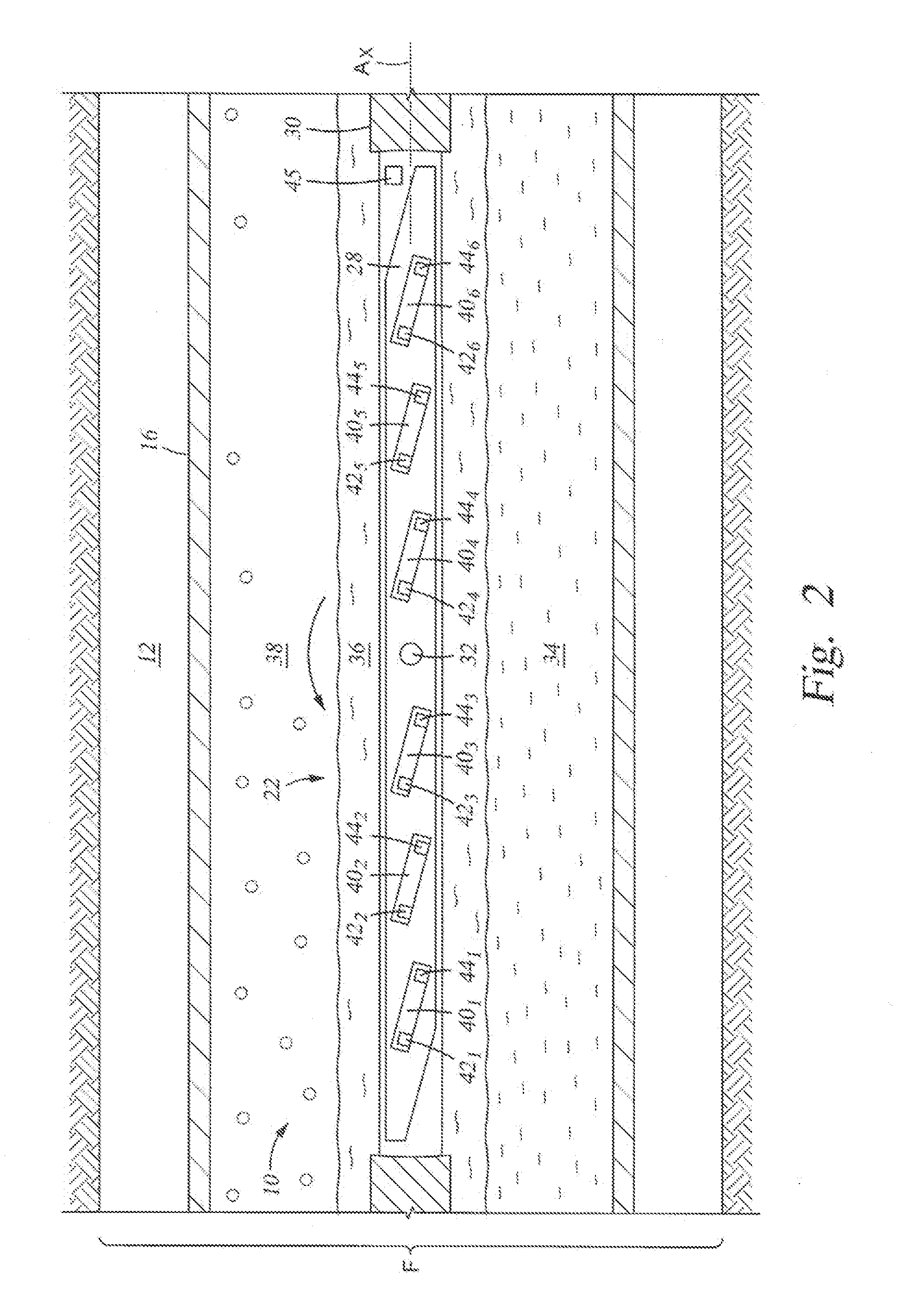
[0006]Also disclosed herein is a system for evaluating fluid flow in a downhole wellbore, and which includes, a thermal source module that is selectively disposed in a flow of fluid in the wellbore and energized to apply thermal energy to the flow of fluid, a thermal sensor module disposed axially away from the thermal source module and disposed in the flow of the fluid in the wellbore downstream of the thermal source module, and that selectively monitors a temperature profile of the fluid over time, and a controller in communication with the thermal sensor module and that selectively identifies a phase of fluid in the (low of fluid based on an analysis of the temperature profile monitored by the thermal sensor module. The thermal sensor module can be a first thermal sensor module, the system further having a second thermal sensor module disposed downstream of the first thermal sensor module and that selectively monitors a temperature profile of the fluid over time. In an example, the controller is in communication with the second thermal sensor module. The system can also include an elongate frame to which the thermal source module and the sensor modules are coupled, and an arm having a length, a width, and a height, and a slot formed radially through the arm, and wherein the frame is coupled in the slot and pivotable about a line that projects along the height of the arm. In an embodiment, the arm mounts to a housing and is pivotal between an orientation substantially parallel with a length of the housing and to an orientation oblique to the length of the housing and that spans across a substantial portion of a diameter of the wellbore. The system can further include an arm having a plurality of thermal source modules each having a corresponding thermal sensor module disposed downstream and each along paths that intersect the thermal source modules and are substantially parallel with an axis of the wellbore.

Problems solved by technology

However, these often require periodic analysis of the fluid entering the flowmeter.
This may involve deploying a sample probe upstream of the flowmeter, which can produce inaccuracy, and may interrupt or temporarily halt fluid production.

Method used


Image

  • Multiphase Thermal Flowmeter for Stratified Flow
  • Multiphase Thermal Flowmeter for Stratified Flow
  • Multiphase Thermal Flowmeter for Stratified Flow

Examples


example

[0025]Table 1 below illustrates values of thermal conductivity, density, heat capacity, density heat capacity, thermal diffusivity, and diffusivity ratio for crude oil, water, and methane over a range of temperature and pressure conditions.

TABLE 1k / (ρεγ)Thermal ConductivityDensityHeat CapacityDensity * Heat CapacityThermal Diffusivity,Diffusivity Ratiok [Wm−3K−1]ρ [kg / m3]cp [jkg−1K−1]ρ [kg / m3] * cp [jkg−1K−1]α [m−2sec−2]α / αCRUDECrude Oil0.125850180015300008.16993E−081.000Water0.5801000418041800001.38756E−071.698Methane (125 C., 8000 psi)0.09821332997020941.40010E−071.714Methane (150 C., 8000 psi)0.10120032936593311.53754E−071.882Methane (175 C., 8000 psi)0.09918933066239261.58477E−071.940Methane (125 C., 5000 psi)0.08817832945868911.49757E−071.833Methane (150 C., 5000 psi)0.08414532464690501.78149E−072.181Methane (175 C., 5000 psi)0.08513532434366331.95640E−072.395Methane (125 C., 10000 psi)0.10824032797867211.37346E−071.681Methane (150 C., 10000 psi)0.10722732907470571.43455E−071.7...


PUM


Abstract

A method and system for evaluating both fluid type and fluid flow downhole by applying thermal energy in a flow of the fluid, and monitoring downstream temperature over time to generate a temperature profile. The type of fluid being evaluated can be determined by comparing the measured temperature profile to profiles over time of known fluids because these profiles depend upon these fluids' thermal diffusivities and flow rates. Further, stratified flow in a deviated wellbore can be analyzed by conducting the fluid evaluation at different radial locations in the flow stream so that the presence of water, liquid hydrocarbons, and gas can he identified. The system can include a pivoting arm that selectively spans the wellbore diameter, and which includes multiple thermal sources, each with corresponding thermal sensor, that are spaced along the arm. A frame can be provided for each of the sources and sensors, which is automatically self-oriented along the direction of fluid flow like a weather vane.

Description

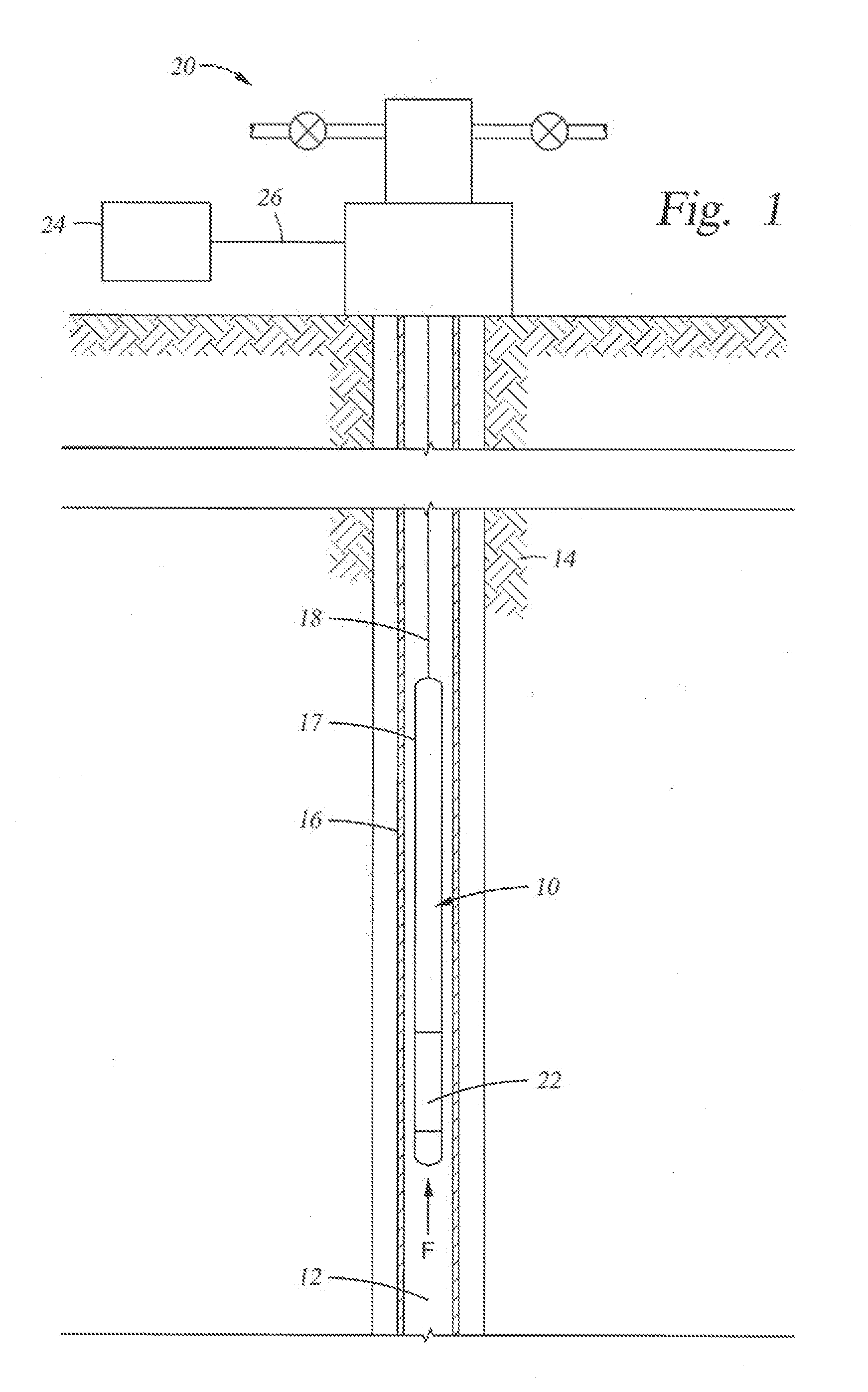
BACKGROUND1. Field of Invention[0001]The invention relates generally to a system and method for evaluating a multiphase flow of wellbore fluids in a tubular. More specifically, the system and method introduces thermal energy into the flow and monitors downstream heating of the fluid to estimate both fluid phase and flow velocity.2. Description of Related Art[0002]Flowmeters are often used for measuring flow of fluid produced from hydrocarbon producing wellbores. Flowmeters may be deployed downhole within a producing wellbore, a jumper or caisson used in conjunction with a subsea wellbore, or a production transmission line used in distributing the produced fluids. Monitoring fluid produced from a wellbore is useful in wellbore evaluation and to project production life of a well. The produced fluid may include water and / or gas mixed with liquid hydrocarbon. Knowing the water fraction is desirable to ensure adequate means are available for separating the water from the produced fluid. ...

Claims


Application Information

Patent Timeline
Patent Type & Authority Applications(United States)
IPC IPC(8): E21B49/08
CPCE21B49/087E21B47/103G01F1/68G01F1/74
Inventor DIFOGGIO, ROCCO
Owner BAKER HUGHES INC
Why Eureka
Try Eureka