

Measuring tool for buildings
- Summary
- Abstract
- Description
- Claims
- Application Information
AI Technical Summary
Benefits of technology
Problems solved by technology
Method used
Image


Examples
Embodiment Construction
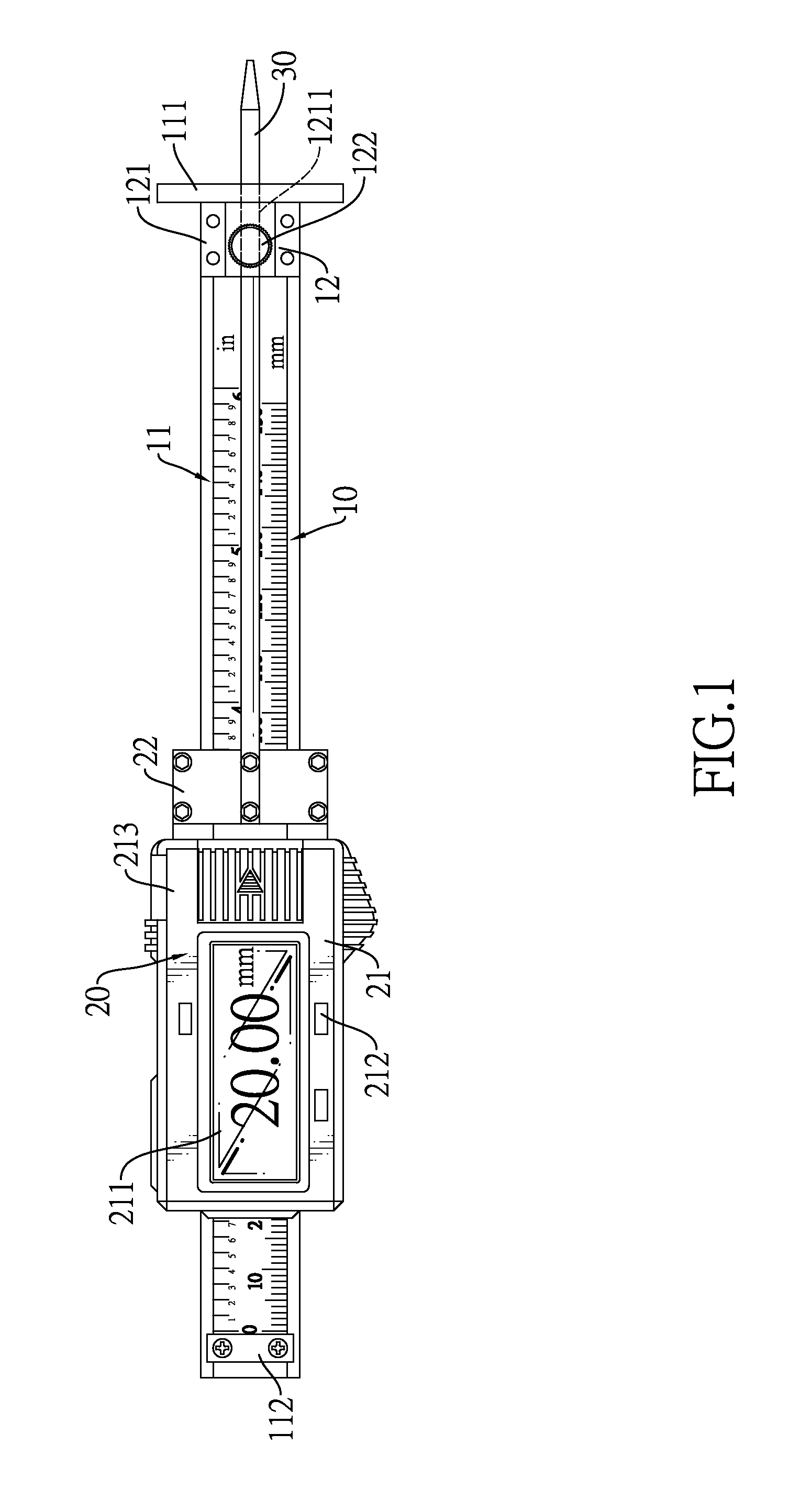
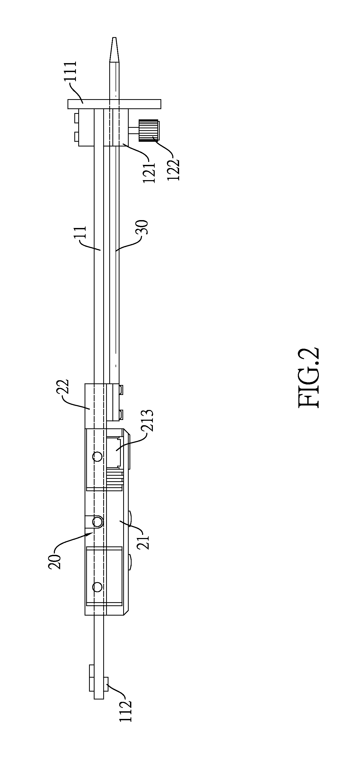
[0019]With reference to FIGS. 1 to 3, a measuring tool for buildings in accordance with the present invention comprises a body 10, an electronic reading device 20, and a probe 30.
[0020]With reference to FIGS. 1 and 2, the body 10 has a plate 11. The plate 11 is elongated in an axial direction, and has a marking surface, two ends, a pushing part 111, and a limiting part 112. The pushing part 111 is perpendicularly connected to one of the ends of the plate 11 and has a pinhole. The limiting part 112 is securely connected to the other end of the plate 11. The plate 11 further has scales marked on the marking surface of the plate 111.
[0021]The body 10 further has a positioning member 12. The positioning member 12 is mounted on the plate 11 and near the pushing part 111. The positioning member 12 has a stationary block 121 and a resisting screw 122. The stationary block 121 is mounted on the plate 11, and the stationary block 121 has a through hole 1211 and a threaded hole. The through h...
PUM
 Abstract
Description
Claims
Application Information