Connecting structure for a check valve

Inactive Publication Date: 2007-03-01
YANG FA MEN INDAL
View PDF4 Cites 6 Cited by
  • Summary
  • Abstract
  • Description
  • Claims
  • Application Information

AI Technical Summary

Benefits of technology

[0010] The check valve may be formed in one-piece with the ear-like chip, its through hole, and the through hole of the protruding part to avoid extra process to improve the effect. Because extra processing can cause error in degree of the preciseness or waste the processing equipment and m

Problems solved by technology

Because extra processing can cause error in degree of the preciseness o

Method used


Image

  • Connecting structure for a check valve
  • Connecting structure for a check valve
  • Connecting structure for a check valve

Examples


Example

[0019] The features and the advantages of the present invention will be more readily understood upon a thoughtful deliberation of the following detailed description of a preferred embodiment of the present invention with reference to the accompanying drawings.

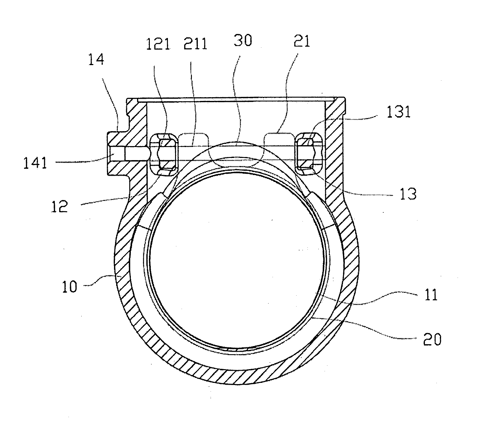
[0020]FIGS. 3 and 4 show the perspective view of the preferred embodiment and the sectional view of the present invention. The connecting structure for the check valve includes a valve base 10 of the check valve and the water-blocking disk 20; the valve base 10 includes a contracted neck 1, two ear-like chips 12, 13 and a protruding part 14, and the protruding part 14 and two ear-like chips 12, 13 have through holes 141, 121, 131 on them; the water-blocking disk 20 includes the U-shaped base 21, and the U-shaped base 21 also has through hole 211; a pin 30 that goes through the through hole 141 of the protruding part 14 and the through hole 121 on the ear-like chip 12, and the through hole 211 of the U-shaped base 21 of the wat...


PUM


Abstract

The connecting structure of the check valve has a mounted water-blocking disk placed on the valve base of the check valve and using a pin connection, an inner wall of the valve having two chips, and through holes on the chips outside the valve base having a protruding part and through hole. The chips and the through holes and the through hole of the protruding part are made in one-piece to avoid extra process to avoid extra process and to avoid the poor effect or error, or waste the processing equipment and tools and time spent on processing. When the water-blocking disk is assembled with the pin, the related positions may be more precise, the movement of the water-blocking disk may be completed correctly and smoothly, and it would not have the problems such as being crooked, not closed and leaking.

Description

RELATED U.S. APPLICATIONS [0001] Not applicable. STATEMENT REGARDING FEDERALLY SPONSORED RESEARCH OR DEVELOPMENT [0002] Not applicable. REFERENCE TO MICROFICHE APPENDIX [0003] Not applicable. FIELD OF THE INVENTION [0004] The present invention relates generally to a connecting structure for check valve, and more particularly to a design with the valve base of the check valve and the pin hole of the water-blocking disk and the U-shaped base of its pin hole, and the U-shaped base and the pin hole are formed in one-piece, so that the degree of preciseness may be more precise in a controllable scope for assembling water-blocking disk, as well as for the movement of the water-blocking disk. BACKGROUND OF THE INVENTION [0005]FIGS. 1 and 2 show the perspective view of the current check valve and the operational view of its processed pin hole. The production of the conventional check valve uses rougher molding technology; first, it molds the shape of basic valve base 1, and its connecting s...

Claims


Application Information

Patent Timeline
IPC IPC(8): F16K15/03
CPCF16K15/03F16K27/0227Y10T137/7903
Inventor YANG, TIAO-HSING
Owner YANG FA MEN INDAL
Why Eureka
Try Eureka