Remote-operated working device and control method

a working device and remote operation technology, applied in the direction of television systems, instruments, cleaning using liquids, etc., can solve the problems of difficult cleaning of places that are beyond human reach, such as exterior walls and windows of buildings

Active Publication Date: 2016-12-29
PANASONIC INTELLECTUAL PROPERTY CORP OF AMERICA
View PDF1 Cites 31 Cited by
  • Summary
  • Abstract
  • Description
  • Claims
  • Application Information

AI Technical Summary

Benefits of technology

[0007]According to the present disclosure, in a case where contact between a working unit and a work target is detected, a signal for vibrating a remote control is transmitted t

Problems solved by technology

Conventionally, it is very difficult to clean a place (e.g., an exterior wall and windows

Method used


Image

  • Remote-operated working device and control method
  • Remote-operated working device and control method
  • Remote-operated working device and control method

Examples


embodiment 1

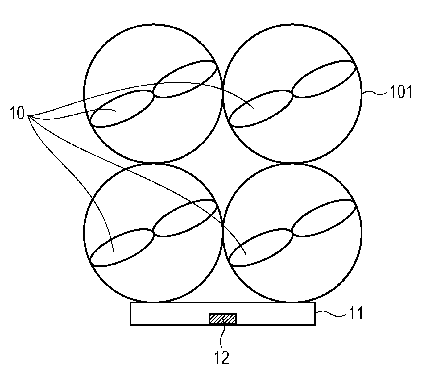
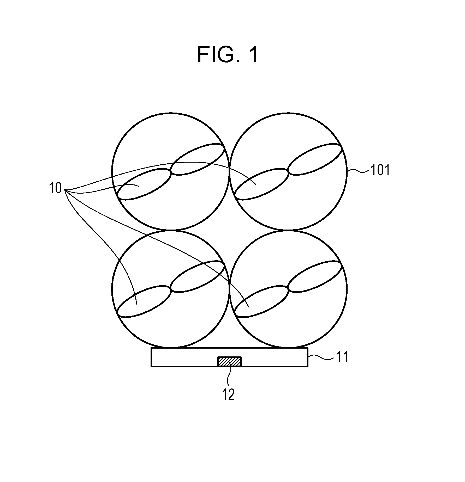
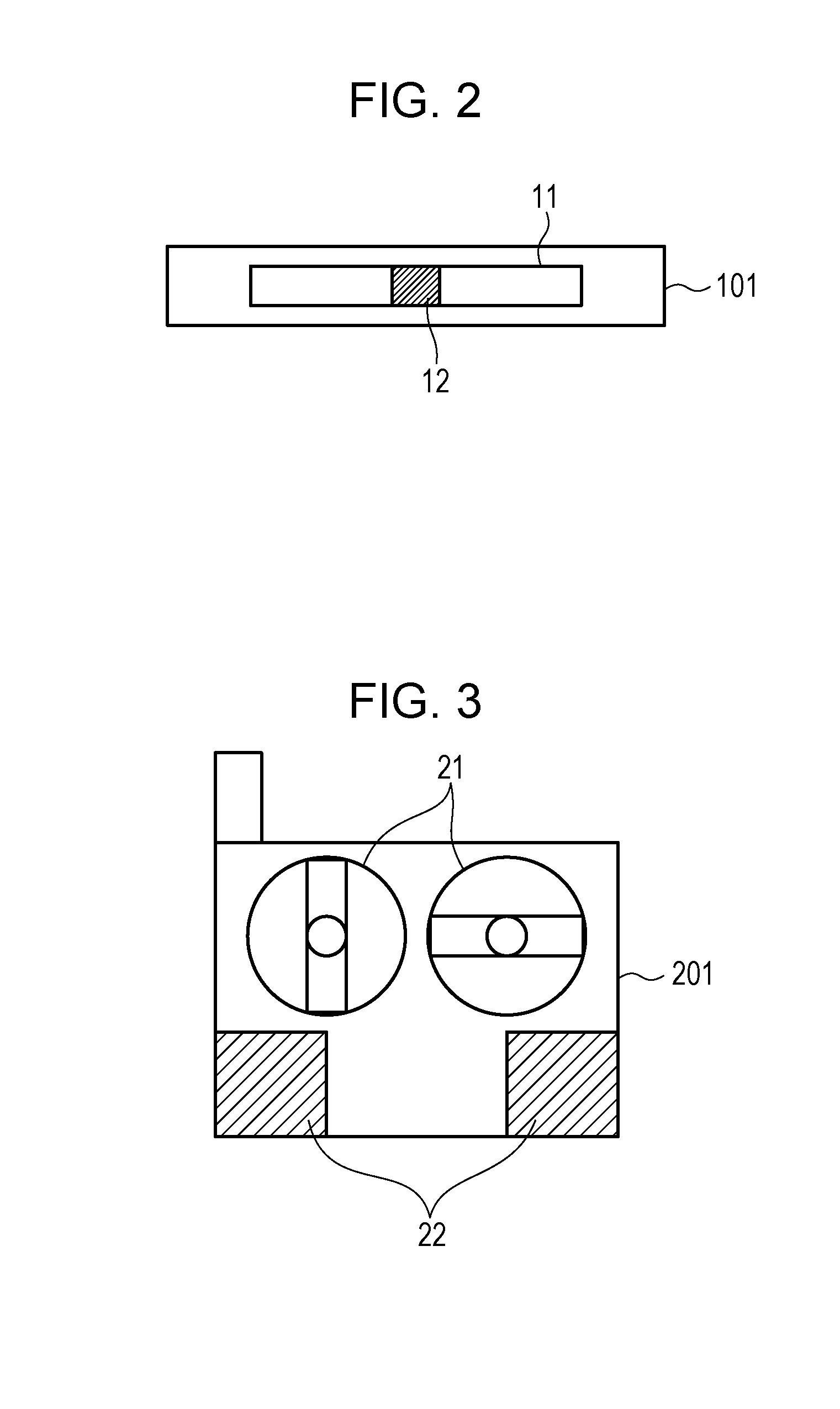
[0097]FIG. 1 is a top view illustrating an exterior configuration of a cleaning robot according to Embodiment 1 of the present disclosure, FIG. 2 is a front view illustrating an exterior configuration of the cleaning robot according to Embodiment 1 of the present disclosure, and FIG. 3 is a front view illustrating an exterior configuration of a remote control according to Embodiment 1 of the present disclosure.

[0098]A cleaning robot (remote-operated working device) 101 illustrated in FIGS. 1 and 2 is remotely operated by a remote control 201 and cleans a target to be cleaned that is in a remote place. The target to be cleaned is, for example, an exterior wall or a window of a house or a building. The target to be cleaned may be, for example, a ceiling. The cleaning robot 101 is an example of a remote-operated working device that is remotely operated by a remote control and performs a predetermined work on a work target in a remote place.

[0099]The cleaning robot 101 is a drone. The c...

embodiment 2

[0137]Next, a cleaning robot according to Embodiment 2 is described. The cleaning robot according to Embodiment 1 includes a single pressure sensor, but the cleaning robot according to Embodiment 2 includes two pressure sensors.

[0138]FIG. 7 is a top view illustrating an exterior configuration of the cleaning robot according to Embodiment 2 of the present disclosure, FIG. 8 is a front view illustrating an exterior configuration of the cleaning robot according to Embodiment 2 of the present disclosure, and FIG. 9 is a front view illustrating an exterior configuration of a remote control according to Embodiment 2 of the present disclosure. In embodiment 2, elements that are identical to those in Embodiment 1 are given identical reference signs, and description thereof is omitted.

[0139]A cleaning robot 102 illustrated in FIGS. 7 and 8 is remotely operated by a remote control 202 and cleans a target to be cleaned that is in a remote place. The target to be cleaned is, for example, an ext...

embodiment 3

[0177]Next, a cleaning robot according to Embodiment 3 is described. In Embodiment 3, the magnitude of vibration of a vibration unit is changed depending on a pressure value detected by a pressure sensor although the magnitude of vibration of a vibration unit is constant in Embodiment 1.

[0178]FIG. 13 is a block diagram illustrating a configuration of a cleaning system according to Embodiment 3 of the present disclosure. The cleaning system illustrated in FIG. 13 includes a cleaning robot 103 and a remote control 203. Exterior configurations of the cleaning robot 103 and the remote control 203 in Embodiment 3 are identical to those illustrated in FIGS. 1 through 3. In Embodiment 3, elements that are identical to those in Embodiment 1 are given identical reference signs, and description thereof is omitted.

[0179]The cleaning robot 103 includes a pressure sensor 12, a communication unit 13, a movement control unit 14, a propeller driving unit 15, and a pressing determining unit 162.

[018...


PUM


Abstract

A remote-operated working device includes a movement controller that controls movement of the remote-operated working device; a working unit that performs a predetermined work on the work target; a first detector that detects contact between the working unit and the target; and a communicator that transmits a signal for vibrating the remote control to the remote control in a case where contact between the working unit and the work target is detected by the first detector.

Description

BACKGROUND[0001]1. Technical Field[0002]The present disclosure relates to a remote-operated working device that is remotely operated by a remote control and performs a predetermined work on a work target that is in a remote place and a control method for controlling the remote-operated working device.[0003]2. Description of the Related Art[0004]Conventionally, it is very difficult to clean a place (e.g., an exterior wall and windows of a building) that is beyond human's reach and to inspect aging of a bridge or a tunnel. For example, Japanese Unexamined Patent Application Publication No. 6-343581 discloses a high-place cleaning remote-controlled robot that includes a cleaning box including a guide rail fixed to a building, a platform main body that moves along the guide rail, a stretchable bar linked to the platform main body, a monitoring camera that is fixed to an end of the bar and takes an image of a cleaning surface, a cleaning tool, a hand to which the tool is attached, and a ...

Claims


Application Information

Patent Timeline
IPC IPC(8): G05D1/00B08B5/04B08B3/02B64C39/02H04N5/247H04N5/33B64D47/08B08B1/00A47L11/10
CPCG05D1/0011B08B1/001B08B5/04B08B3/02B08B1/002A47L11/10B64C2201/123H04N5/33B64D47/08B64C39/024A47L2201/04B64C2201/12B64C2201/108H04N5/247G05D1/0246H04N23/695B64U10/13B64U2101/26B64U2101/30G05D1/0016G05D1/005G05D2201/0203E04G23/002A47L2201/00B08B13/00B25J11/0085H04N23/667H04N23/63H04N23/90B64U2201/20B64U2101/00
Inventor TANIGAWA, TORU
Owner PANASONIC INTELLECTUAL PROPERTY CORP OF AMERICA
Why Eureka
Try Eureka