Control circuit and control method for illumination apparatus

Inactive Publication Date: 2016-12-29
ROHM CO LTD
View PDF11 Cites 19 Cited by
  • Summary
  • Abstract
  • Description
  • Claims
  • Application Information

AI Technical Summary

Benefits of technology

[0041]Examples of such a “monolithically integrated” arrangement include: an arrangement in which all the circuit components are formed on a semiconductor substrate; and an arrangement in which principal circuit components are monolithically integrated. Also, a part of the circuit components such as resistors and cap

Problems solved by technology

Such a reduction in the luminance is recognized by viewers as screen flicker, which is a problem.
However, this leads to a problem of increased power consumption and increased heat generation.
Furthermore, in a case in which the feedback loop has a wide bandwidth, this leads to degraded phase characteristics, resulting in a reduction in the stability of the fee

Method used


Image

  • Control circuit and control method for illumination apparatus
  • Control circuit and control method for illumination apparatus
  • Control circuit and control method for illumination apparatus

Examples


Example

[0098]With the first embodiment, in the normal lighting period TNORM after the calibration period TCAL, the error signal generating unit 220 is fixed to the second state φ2 in which the output voltage VOUT is maintained at a constant level. In contrast, with the second embodiment, in the normal lighting period TNORM, the control logic 240 operates while dynamically and adaptively switching the error signal generating unit 220 between the first state φ1 and the second state φ2.

[0099]More specifically, in a case in which there is a small fluctuation in the output voltage VOUT if the first state φ1 is selected in the normal lighting period TNORM, the control logic 240 instructs the error signal generating unit 220 to operate in the first state φ1 even in the normal lighting period TNORM.

[0100]FIG. 7A is a diagram showing the forward voltages VF of the multiple LED bars when the dimming pulses SDIM each have a narrow pulse width. FIG. 7B is a diagram showing such forward voltages VF whe...


PUM


Abstract

An error signal generating unit is configured such that (i) in a calibration period, the error signal generating unit is set to a first state in which it amplifies an error signal by amplifying a difference between a predetermined first reference voltage and the lowest one from among multiple first detection voltages, and such that (ii) after the calibration period, the error signal generating unit is set to a second state in which it generates the error signal by amplifying a difference between a second detection voltage and a second reference voltage. A reference voltage setting unit holds, as the second reference voltage, the largest value of the second detection voltage detected in the calibration period.

Description

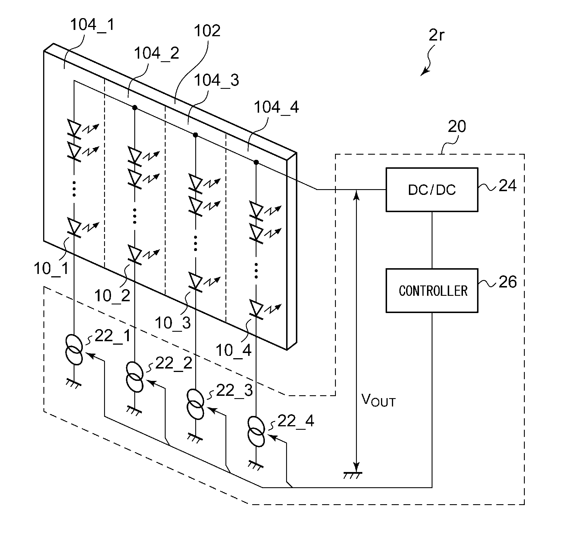
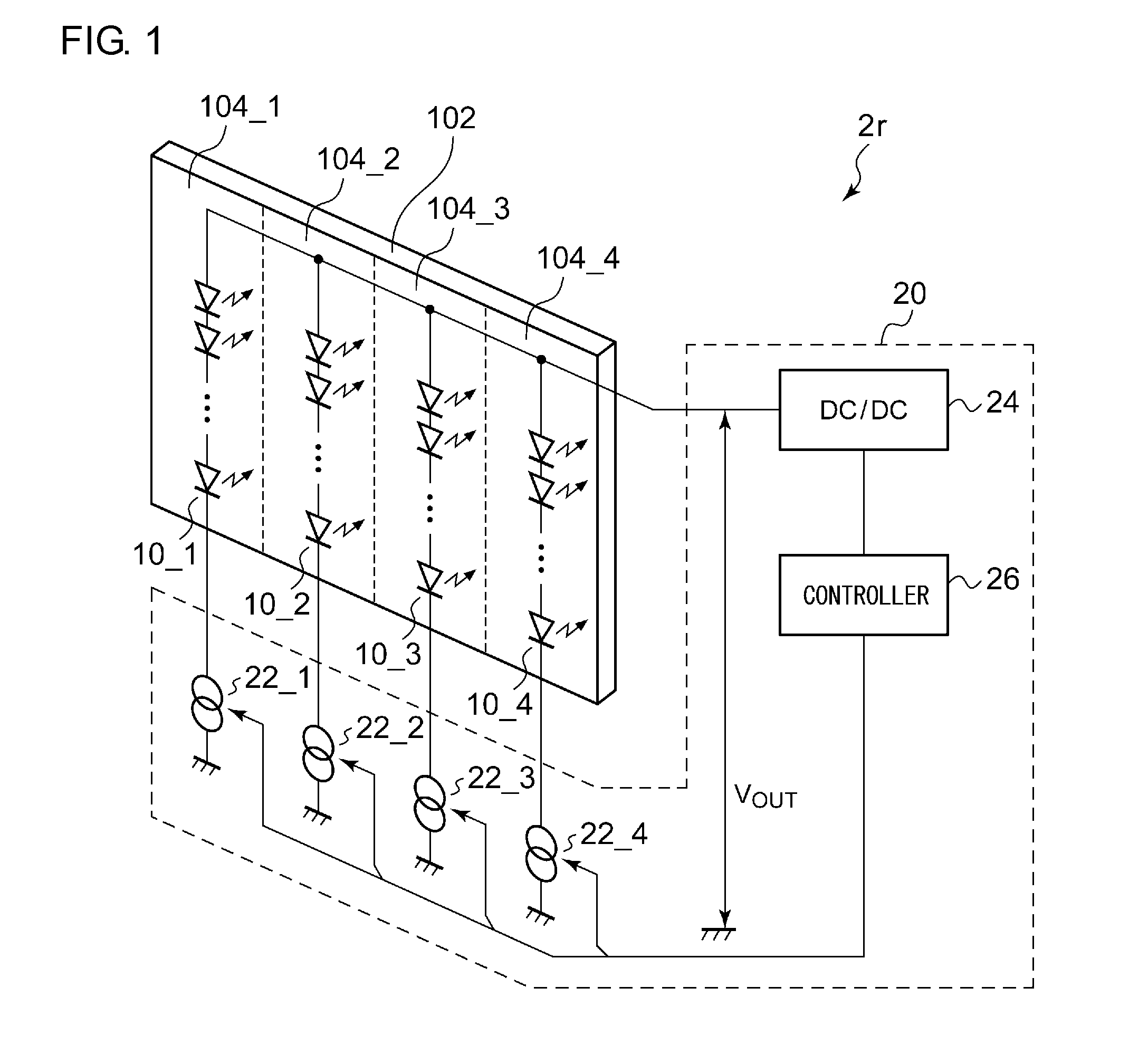
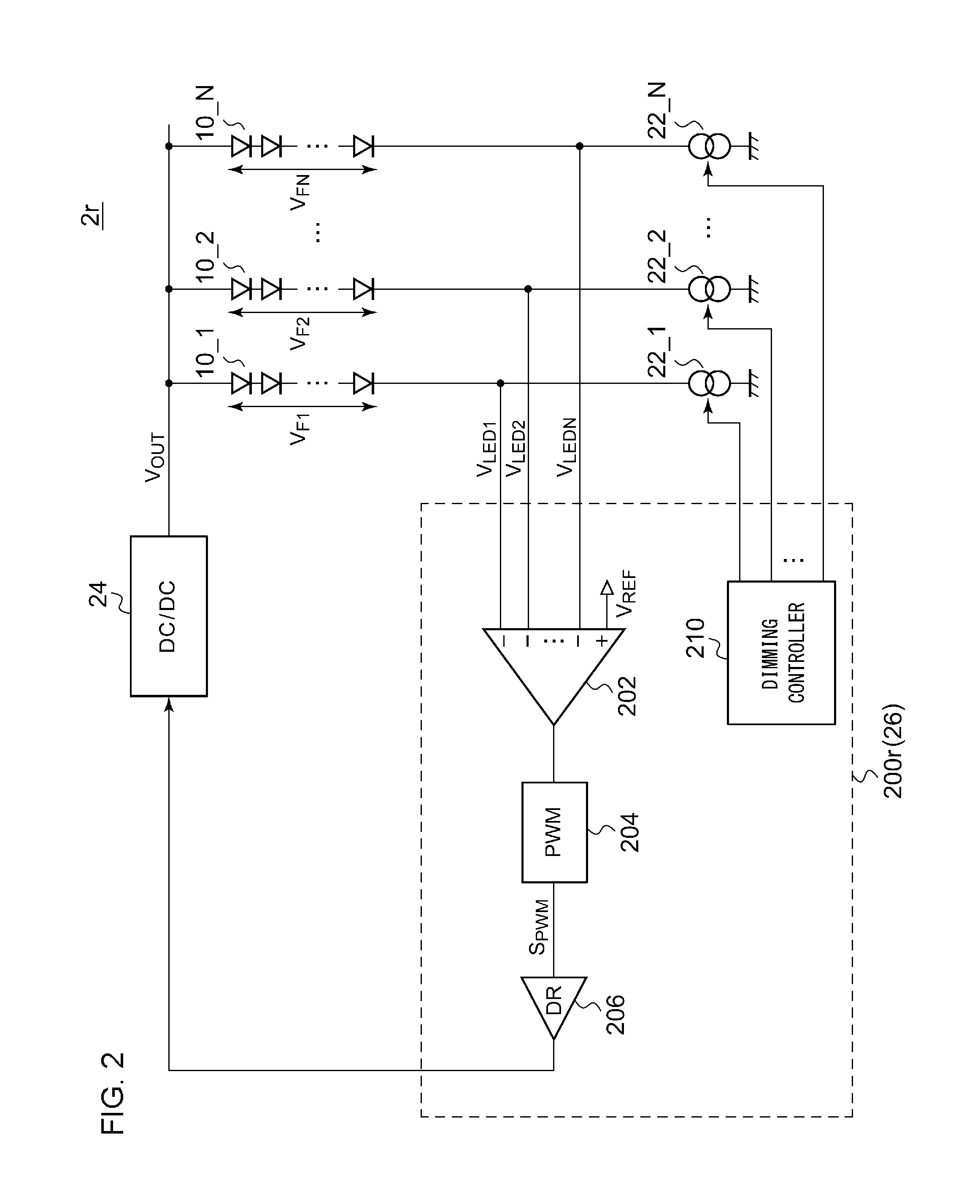
CROSS REFERENCE TO RELATED APPLICATIONS[0001]The present invention claims priority under 35 U.S.C. §119 to Japanese Application No. 2015-125801, filed Jun. 23, 2015, the entire content of which is incorporated herein by reference.BACKGROUND OF THE INVENTION[0002]Field of the Invention[0003]The present invention relates to a driving technique for a light-emitting diode.[0004]Description of the Related Art[0005]As a backlight for a liquid crystal display (LCD) panel, white light-emitting diodes (which will be simply referred to as “LEDs” hereafter) having favorable properties from the perspective of a long operating life, low power consumption, and a wide color range are employed.[0006]FIG. 1 is a diagram showing a backlight illumination apparatus 2r investigated by the present inventors. FIG. 1 shows an LCD panel 102 in addition to the illumination apparatus 2r. The illumination apparatus 2r is configured as a direct-type illumination apparatus. The illumination apparatus 2r includes...

Claims


Application Information

Patent Timeline
IPC IPC(8): H05B33/08G09G3/36G09G3/34H05B44/00
CPCH05B33/0815H05B33/083H05B33/0845G09G3/342G09G2320/0252G09G2330/021G09G2320/064G09G2310/06G09G2320/0247G09G3/36G09G2320/0693H05B45/20H05B45/46H05B45/347H05B45/3725H05B45/48
Inventor HAGINO, JUNICHI
Owner ROHM CO LTD
Why Eureka
Try Eureka