Adjustable clamp on head bracket

Active Publication Date: 2017-01-05
CNH IND CANADA
View PDF7 Cites 3 Cited by
  • Summary
  • Abstract
  • Description
  • Claims
  • Application Information

AI Technical Summary

Benefits of technology

The present invention provides a common tool bar for different sized planters, which alleviates tool bar clutter and facilitates the repositioning of row unit head brackets. Additionally, blank tool bars and appropriate row unit completing kits allow farmers to custom build a planter.

Problems solved by technology

Tool bars are becoming increasingly crowded.
Today with all of the obstructions on top of the bar (vacuum systems, hydraulic systems, and other structures) modifying the planter configuration is difficult.

Method used


Image

  • Adjustable clamp on head bracket
  • Adjustable clamp on head bracket
  • Adjustable clamp on head bracket

Examples


Embodiment Construction

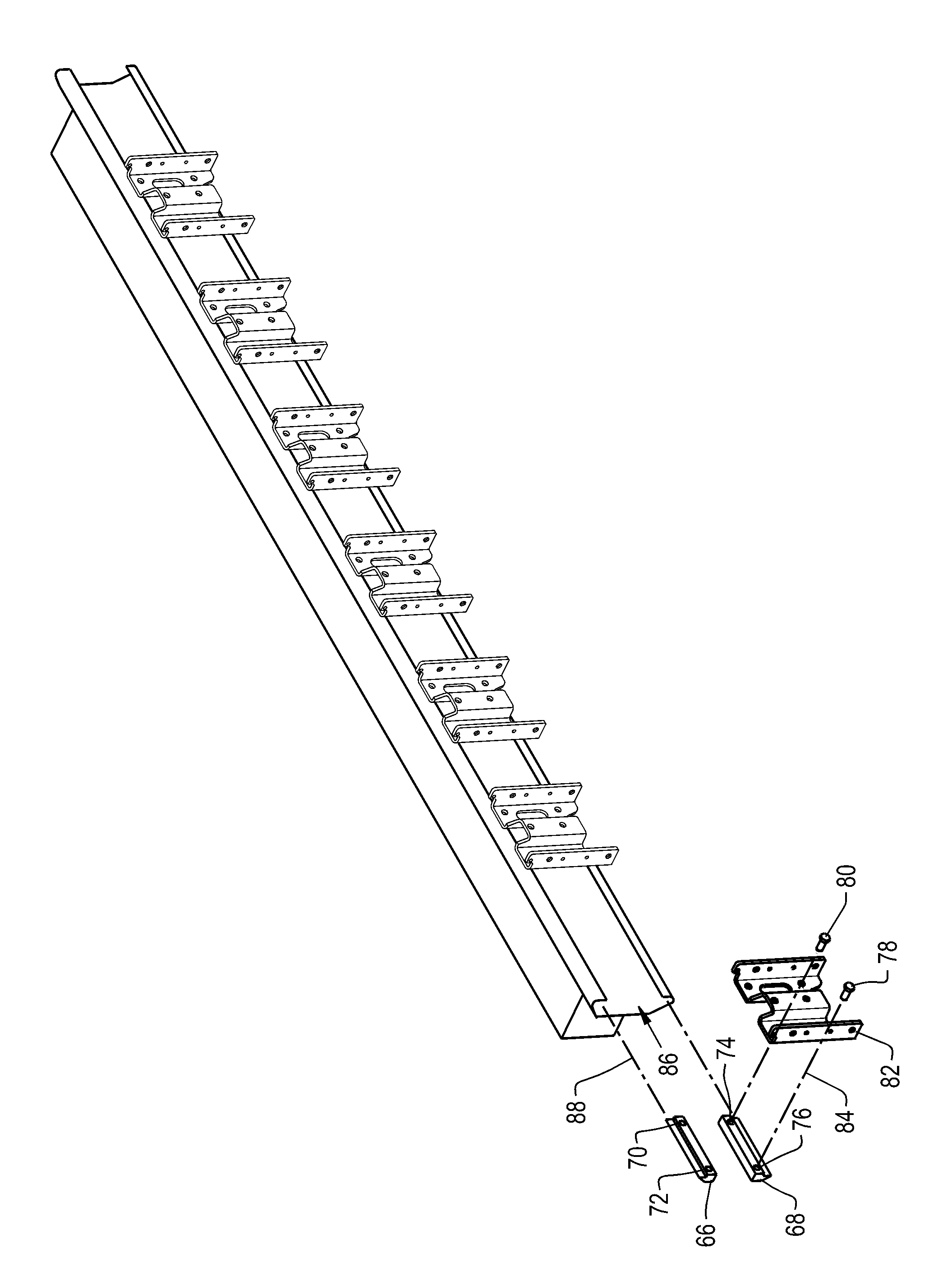
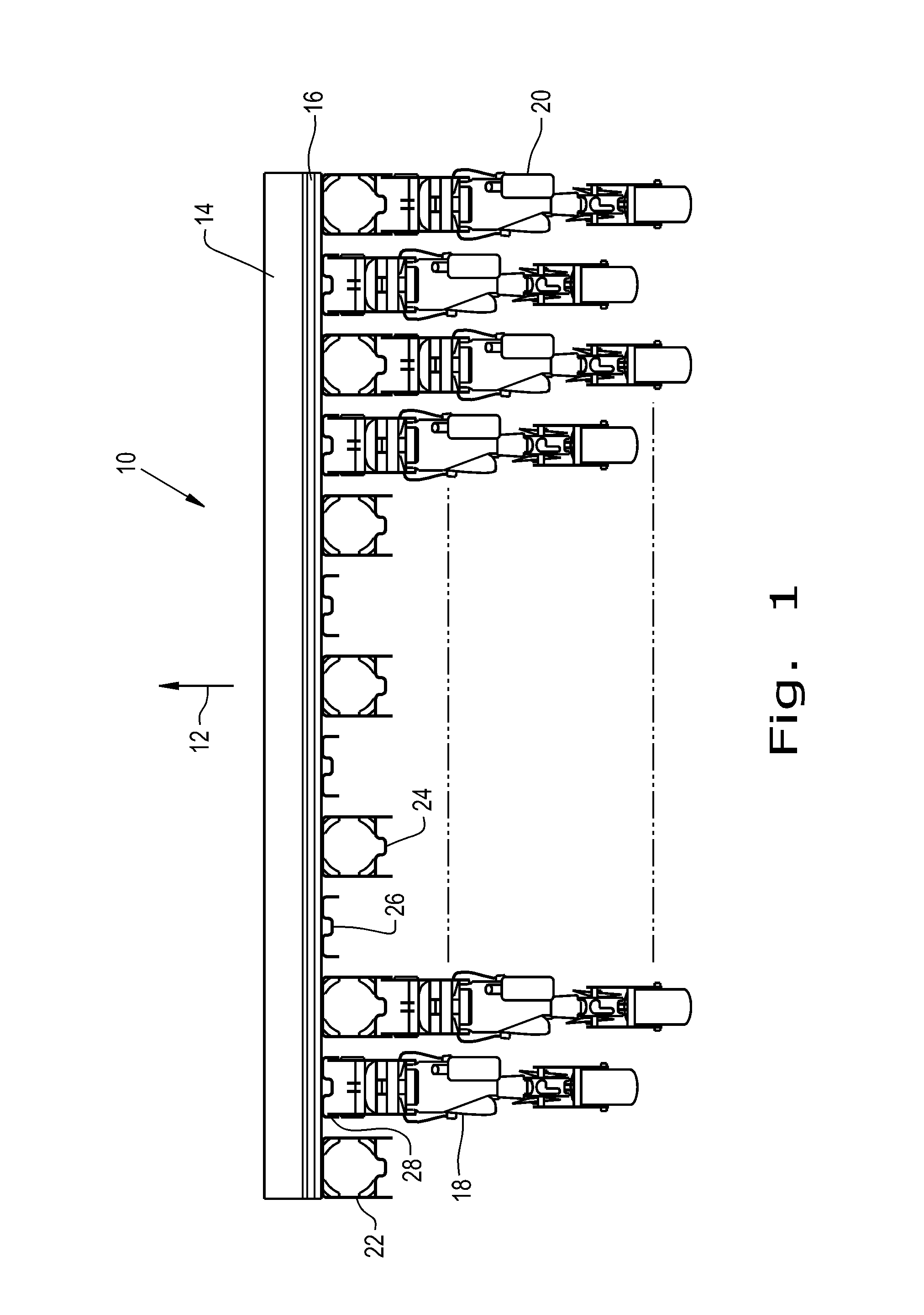
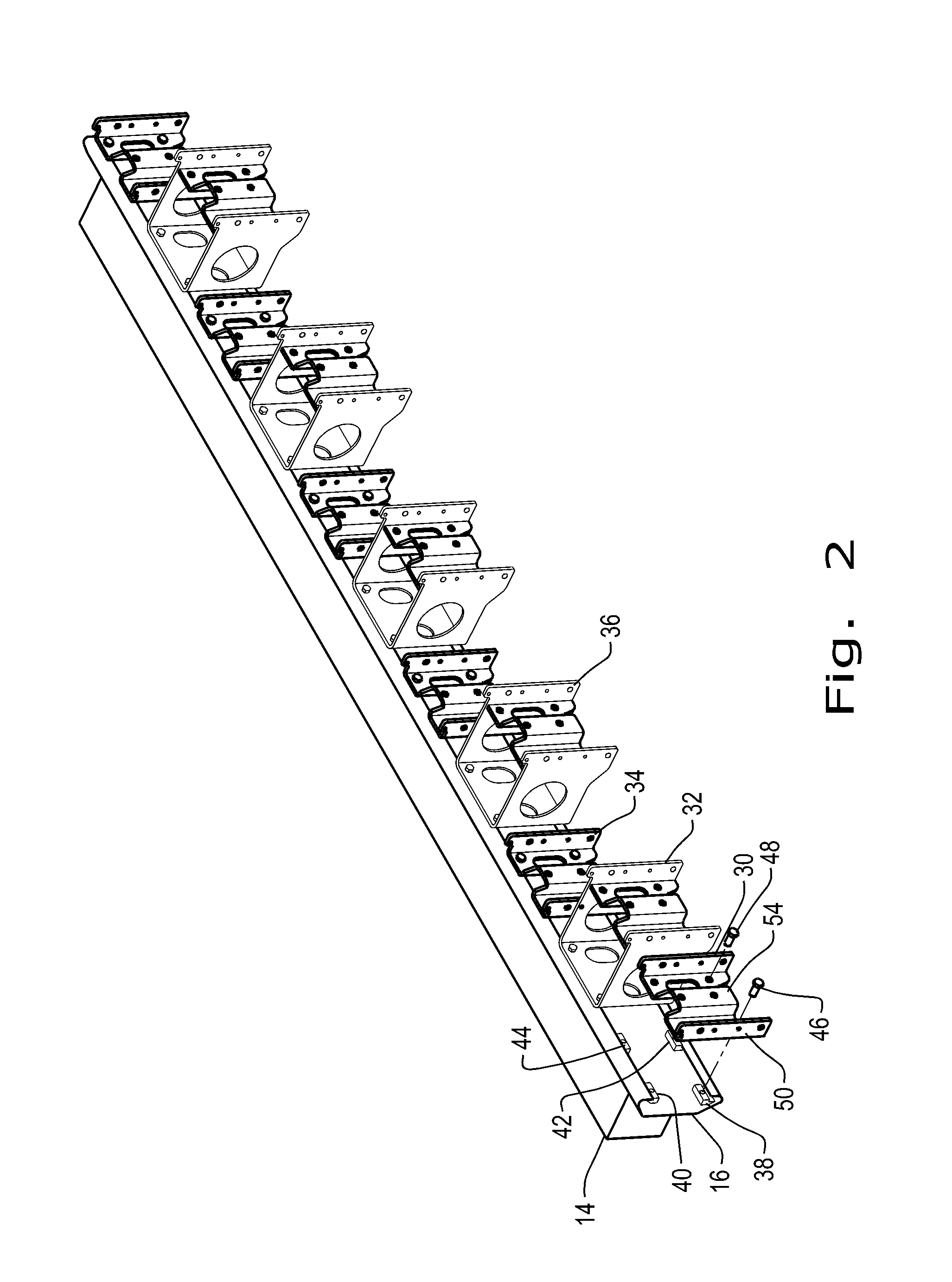
[0027]Referring now to the drawings, and more particularly to FIG. 1, there is shown a portion of a planter 10 or similar agricultural implement which may be towed generally in the direction of arrow 12. The implement includes a tool bar 14 to which an elongated channel 16 of generally C-shaped cross-section is fixed as by welding along the closed edge of the “C”. As noted earlier, many planting implements are too wide for transport on highways, entry to farm fields through gates, or for barn storage. These may have a relatively fixed central portion with additional portions extending laterally as wings which may be pivoted and / or rotated to a stowed position for transport or storage. The tool bar 14 illustrated may either form part of such a central portion or part of a wing.

[0028]A number of illustrative row units such as 18 and 20 are shown. The configuration illustrated would be for planting narrow spaced rows of crop, e.g., beans. The illustrated row units are conventional and ...


PUM


Abstract

The selective positioning of row units along a planter tool bar is facilitated by introducing an elongated channel of generally C-shaped cross-sectional configuration intermediate the tool bar and a plurality of row unit head brackets. The channel is welded or otherwise fixed to the tool bar with the open edge of the “C” facing away from the tool bar and the head brackets are fixed to the channel by clamping nut and bolt assemblies. The bolts extend through the clamping brackets and engage corresponding clamping nuts. The clamping nuts are positioned within the “C” and may be slid along the inner edge of the channel to any preferred position. The bolts are then and tightened fixing the head bracket at the selected at location.

Description

BACKGROUND OF THE INVENTION[0001]1. Field of the Invention[0002]The present invention relates to ground working equipment, such as an agricultural implement, and, more particularly, to a system for attaching row units on an agricultural implement.[0003]2. Description of the Related Art[0004]Generally, planting implements (e.g., planters) are towed behind a tractor or other work vehicle via a mounting bracket secured to a rigid frame (tool bar) of the implement. These planting implements typically include multiple row units distributed across the width of the implement. Each row unit is configured to deposit seeds at a desired depth beneath the soil surface, thereby establishing rows of planted seeds. For example, each row unit may include a ground engaging tool that forms a seeding path for seed deposition into the soil. As the implement travels across a field, the opener excavates a trench into the soil, and seeds are deposited into the trench. Individual row units are usually atta...

Claims


Application Information

Patent Timeline
IPC IPC(8): A01B59/00A01C7/08
CPCA01C7/08A01B59/002A01B15/14A01C7/201
Inventor GADZELLA, GERARD JAMESPRICKEL, MARVIN A.CONNORS, MICHAEL J.
Owner CNH IND CANADA
Why Eureka
Try Eureka