Fuel nozzle with flexible support structures

Active Publication Date: 2017-01-05
GENERAL ELECTRIC CO
View PDF6 Cites 14 Cited by
  • Summary
  • Abstract
  • Description
  • Claims
  • Application Information

AI Technical Summary

Benefits of technology

[0006]Furthermore, the entire fuel nozzle is subject to significant vibration at various frequencies. The internal support structures of the fuel nozzle must be stiff enough

Problems solved by technology

Furthermore, the entire fuel nozzle is subject

Method used


Image

  • Fuel nozzle with flexible support structures
  • Fuel nozzle with flexible support structures
  • Fuel nozzle with flexible support structures

Examples


Embodiment Construction

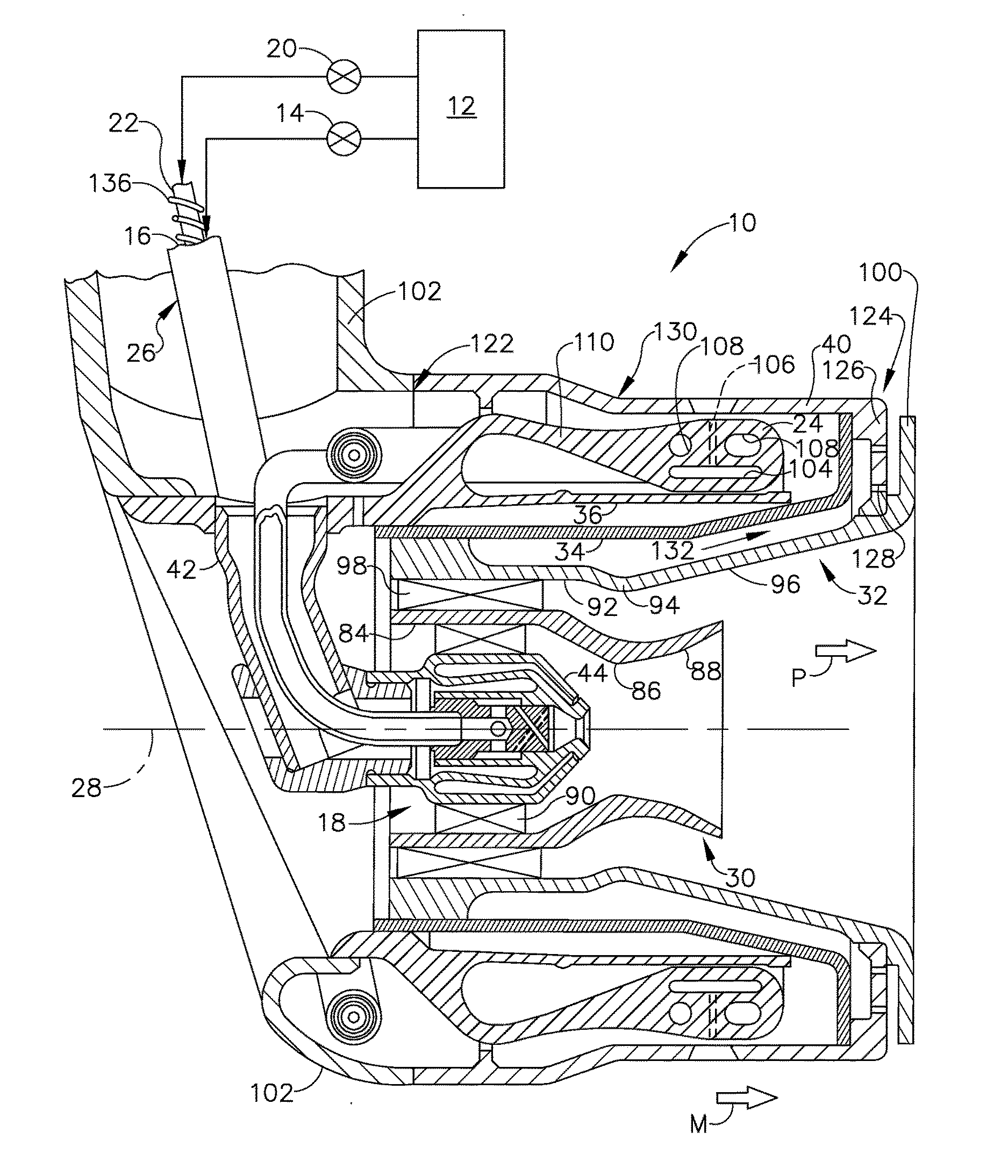
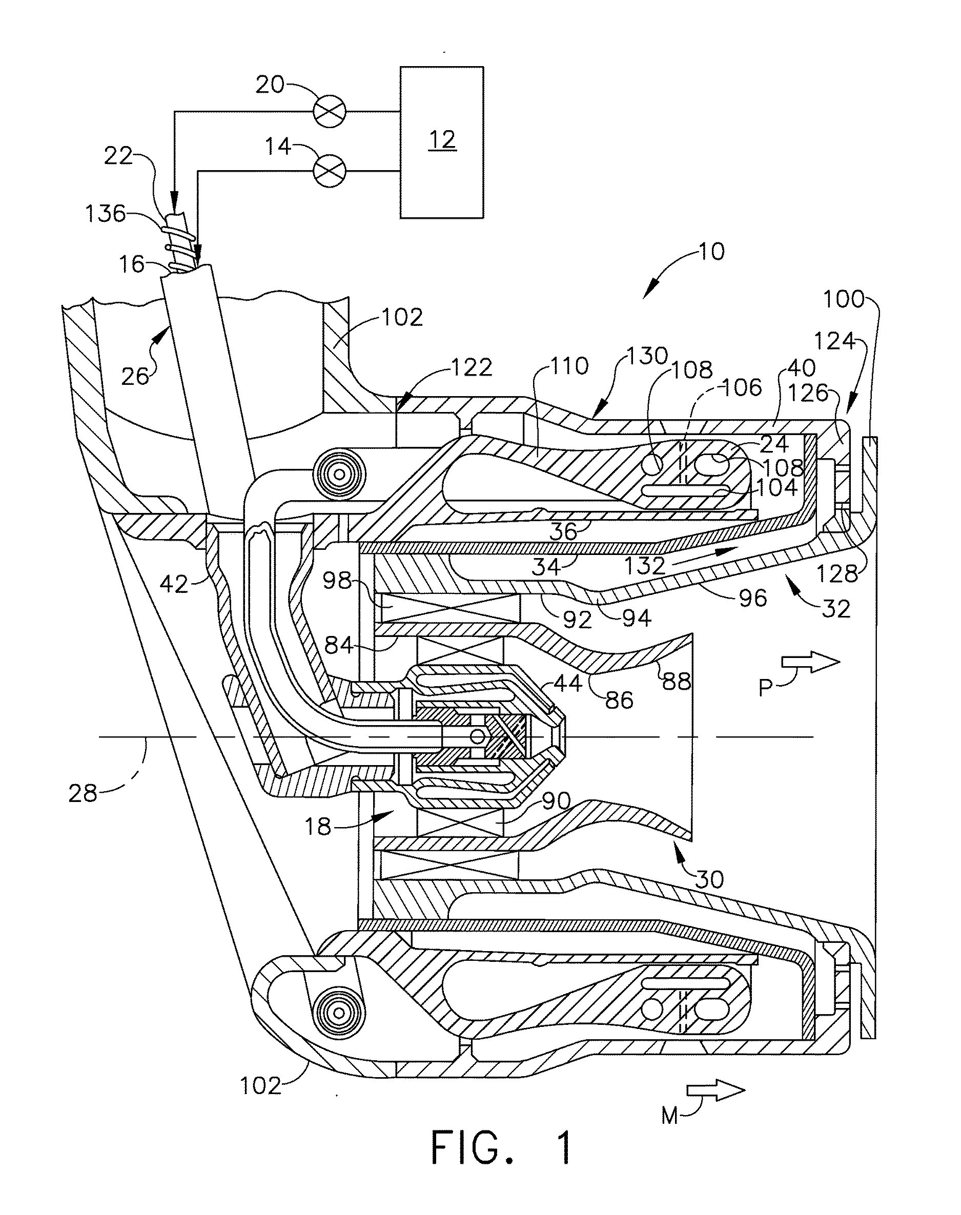
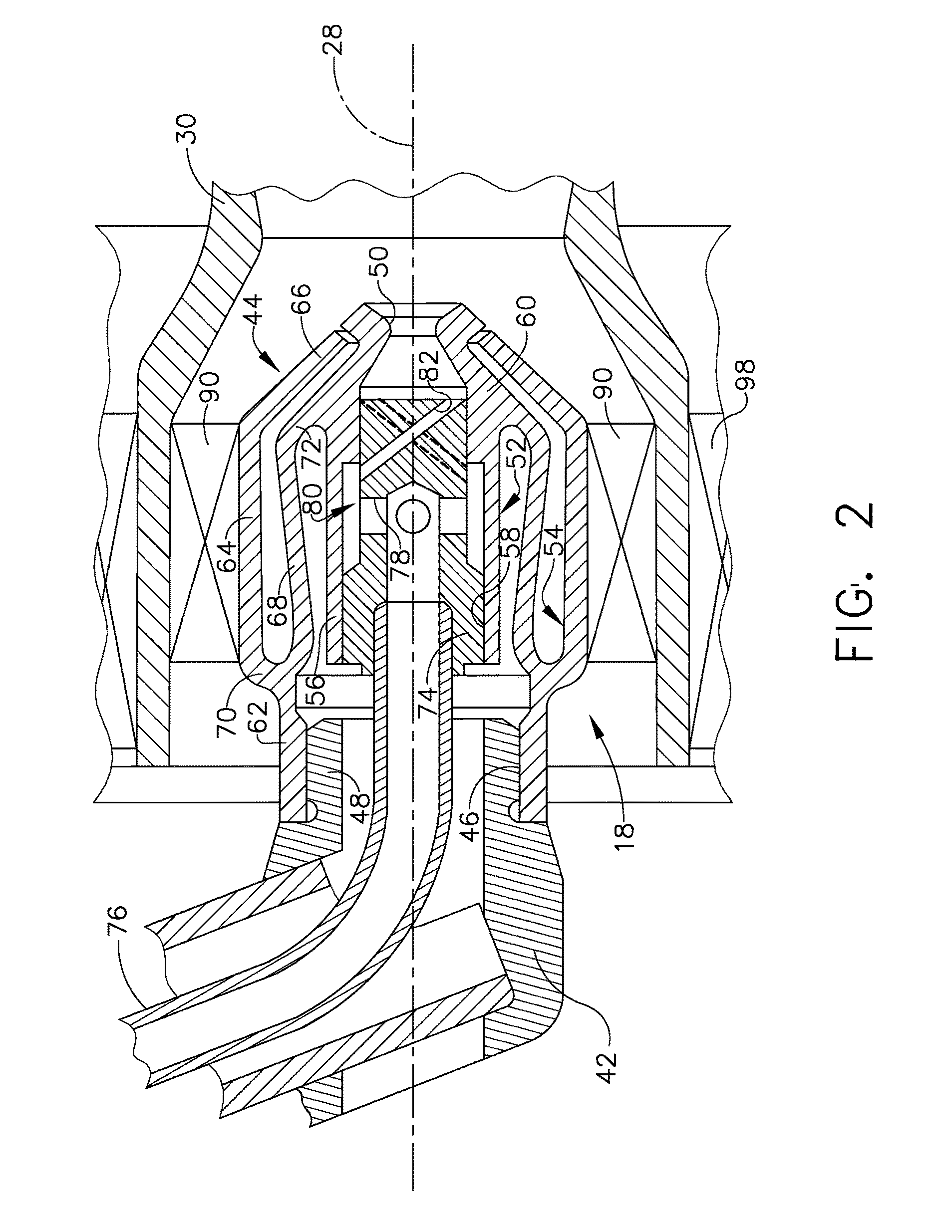
[0023]Generally, the embodiments of the present invention provide a staged fuel nozzle incorporating one or more flexible support structures to provide structural support for other elements of the fuel nozzle. As used herein, the term “flexible support structure” generally refers to a structure that exhibits flexibility and resilience attributable to its physical shape and size, and generally refers to relatively thin, elongated structures. The purpose of the flexible support structure is to provide physical support for an attached structure while maintaining stresses in the support structure at acceptable levels during various operation conditions, especially during temperature changes. An alternative term for “flexible support structures” is “stress-tailored support structure.” The principles of the embodiments of the present invention could also be applied to other types of fuel nozzles, including those which are not staged.

[0024]Now, referring to the drawings wherein identical r...


PUM


Abstract

A fuel nozzle apparatus for a gas turbine engine includes: a fuel discharge element having a discharge orifice communicating with a fuel supply connection; a static supporting structure; and a cantilevered flexible support structure interconnecting the supporting structure and the fuel discharge element, the flexible support structure having a first end connected to the static supporting structure, and a second end connected to the fuel discharge element.

Description

CROSS-REFERENCE TO RELATED APPPLICATIONS[0001]This application is a national stage application under 35 U.S.C. §371(c) of prior filed, co-pending PCT application serial number PCT / US2014 / 072028, filed on Dec. 23, 2014 which claims priority to U.S. provisional patent application 61 / 920,018, titled “FUEL NOZZLE WITH FLEXIBLE SUPPORT STRUCTURES”, filed on Dec. 23, 2013. The above-listed applications are herein incorporated by reference.BACKGROUND[0002]Embodiments of the present invention relate to gas turbine engine fuel nozzles and, more particularly, to apparatus for supporting various structures within turbine engine fuel nozzles.[0003]Aircraft gas turbine engines include a combustor in which fuel is burned to input heat to the engine cycle. Typical combustors incorporate one or more fuel injectors whose function is to introduce liquid fuel into an air flow stream so that it can atomize and burn.[0004]Staged combustion systems have been developed to limit pollution, increase efficie...

Claims


Application Information

Patent Timeline
IPC IPC(8): F23R3/28F23R3/34F23R3/14
CPCF23R3/28F23R3/343F23D11/386F23R3/14F23R3/283Y02T50/60
Inventor MOOK, JOSHUA TYLERBELLARDI, JASON JOSEPHTU, TING-YU
Owner GENERAL ELECTRIC CO
Why Eureka
Try Eureka