
Method of sealing a joint

a joint and sealing technology, applied in the direction of engine seals, aircraft components, engine components, etc., can solve the problems of increasing the weight of the aircraft, affecting the sealing effect, and laborious pre-mixing of sealant components, so as to achieve high load-transferring, high fatigue resistance, and efficient sealing

Inactive Publication Date: 2006-08-31
AIRBUS OPERATIONS LTD
View PDF21 Cites 7 Cited by
  • Summary
  • Abstract
  • Description
  • Claims
  • Application Information

AI Technical Summary

Benefits of technology

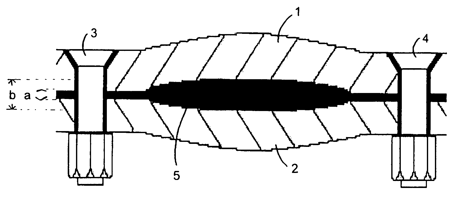
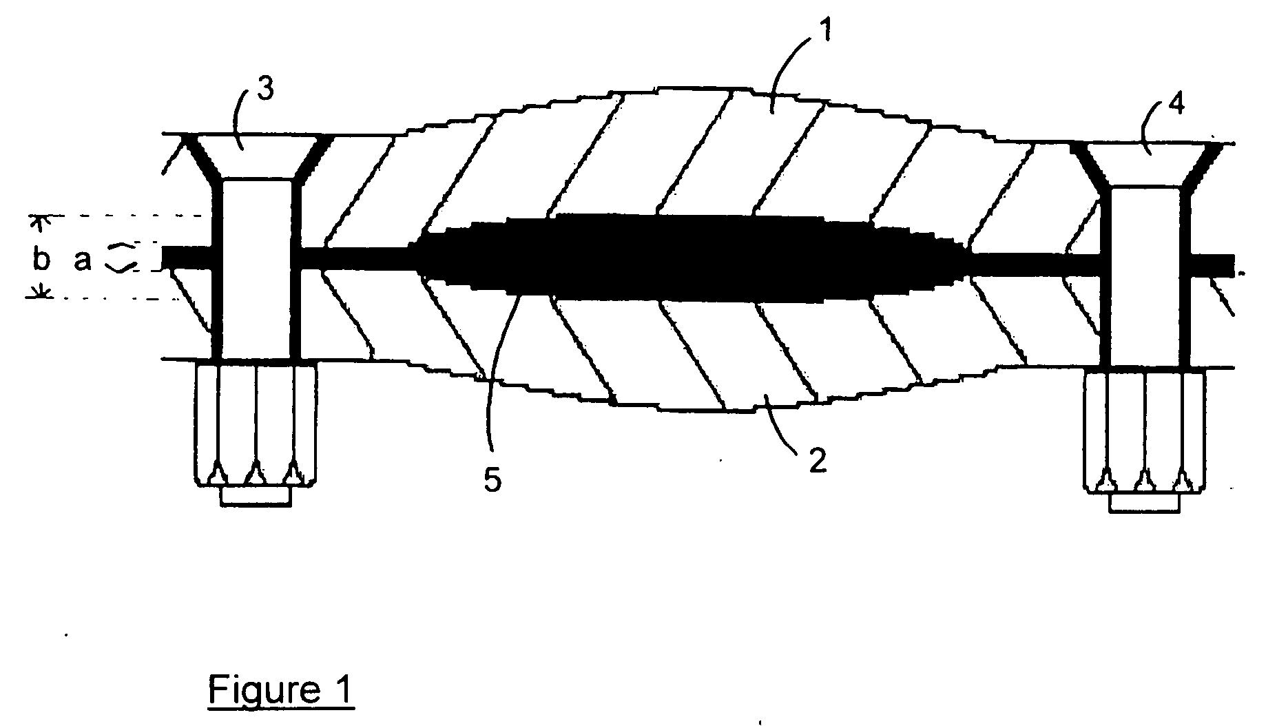
[0026] Knowledge of the above, and, in particular, of the fractional minimum sealing thickness and the fractional fully compressed thickness associated with a particular sealing material allows, in accordance with the invention, a sealing material thickness to be chosen. For example, in accordance with the method of the invention a minimum thickness of the sealing material is calculated and at least that minimum thickness of sealing material is used in the joint. In one embodiment, the process of the invention allows the use of data from material tests to be used to develop sealing material sheets, gaskets, tapes and the like which best fill voids whilst giving minimum joint stand-off to achieve a highly fatigue-resistant, high load-transferring, efficient sealing system with a maximum sealing range.
[0028] In such an interfay joint, shear of fasteners and friction between joint faces in contact can help to transfer loading between the metal components, despite the potential for fretting to occur. Loading can also be transferred from one metal component to the other through the cured sealant, which has elastomeric properties. However, the degree of loading transfer through the sealant will be limited because the shear modulus (stiffness) of the cured sealant is relatively low.
[0029] In joints assembled according to the process of the present invention, there is a finite joint stand-off, which will in most cases be at least 0.25 mm with no component-to-component contact occurring. In such joints, fretting is eliminated but load transfer by direct contact of the metal component faces is also prevented. The loading must therefore be transferred only through the fasteners and the sealing material. The overall effect is to give a more consistent fatigue performance of the joints. However, the degree of load transfer through the sealing material will decrease with increasing thickness of the sealing material, and accordingly, it will not in general be desirable to use very large thicknesses of sealing material.
[0032] The selected suitable thickness of the sealing material may be the minimum thickness calculated, for example, where it is desired to reduce weight and / or cost to a minimum. Alternatively, it may be desired to use a thickness of sealing material which is greater than that minimum thickness to allow a safety margin thereby allowing for such factors as errors in measurement, variation in the manufacturing process and movement in the joint over time.
[0047] The effective sealing range, that is, the difference between the fully-compressed thickness and the maximum sealing thickness, can be increased for the same volume of sealing material by profiling or embossing a pattern in relief on the surface of the sealing material. The sealing material may be profiled or embossed on one side only. Alternatively, the sealing material may be profiled or embossed on both sides.
[0049] In a further aspect, the invention provides a sealing material having regions of differing thickness, the regions of differing thickness being arranged such that the effective sealing range of the sealing material is greater than the effective sealing range of a sealing material having the same mean thickness and the same composition and having a uniform thickness. The use of such a sealing material having regions of differing thickness makes possible the sealing of larger sealing gaps than could have been sealed using the same amount of a similar sealing material having a uniform thickness.

Problems solved by technology

In general, the polysulphide sealants are currently used in aircraft manufacture are two-component systems, with the mixing of the components being done shortly before use of the sealant (one-component polysulphide sealants are known but do not, in general, meet the demanding requirements for use in aircraft).
the premixing of the sealant components prior to use is labour-intensive, messy and requires accurate control and measurement of the levels of curing promoter in order to ensure that the period during which the sealant remains workable (the “work life”) is sufficient for the planned joint assembly;
during tightening of the bolts, the liquid sealant is squeezed away from the immediate vicinity of each bolt thereby allowing direct contact of the components such that subsequent relative movement of the components during the lifetime of the aircraft can cause the paint to rub off, leaving the joint vulnerable to corrosion (this is known as “fretting”).
However, using such an increased thickness of sealing material increases the weight of the aircraft, involves additional cost and reduces any contribution to the stiffness of the joint made by the sealing material.

Method used


Image

  • Method of sealing a joint
  • Method of sealing a joint
  • Method of sealing a joint

Examples


example 1

[0062] A joint was specified to have a maximum joint face separation in the quilted areas between the bolts of 0.25 mm. Thus, the sealing gap for the joint was 0.25 mm. A suitable sealant material was found in tests to have a fractional maximum sealing thickness of 80% and a fractional fully compressed thickness of 40%.

[0063] In order to seal effectively over the whole joint, a thickness of sealing material must be used such that the effective sealing range is at least equal to the sealing gap of 0.25 mm. Thus 0.25 mm must be equal to (80%−40%)=40% of the minimum thickness, that is, the uncompressed thickness of the sealing material must be at least 0.625 mm. Using a sealing material of thickness 0.625 mm (100%) would give a maximum joint face separation of 0.5 mm (80%) and ajoint stand-off of 0.25 mm (40%).

example 2

[0064] In the joint described in Example 1, a 1.1 mm thickness of the same sealing material is used. The effective sealing range is 1.1 mm×(0.8−0.4)=0.44 mm. That effective sealing range is 0.19 mm greater than the required sealing range of 0.25 mm but that margin may be desired to allow for surface defects and movement. The joint stand-off is 1.1 mm×0.40=0.44 mm.

example 3

Preparation of a Reinforced Polysulphide Sealing Material

[0065] A conventional manganese dioxide polysulphide sealant, Chemetall MC238-A1 / 2 having a faster cure time than is normally used in airframe assembly (½ hour work-life grade), was mixed and evenly applied to a 200 mm×200 mm release sheet of PTFE. A 150 mm×150 mm square of 120 gram per square meter woven glass-fibre cloth of maximum thickness 0.25 mm was placed over the smoothed out sealant layer. Sealant was worked through the woven glass cloth using a plastic spatula (to remove entrapped air) and a second layer of sealant was smoothed over the glass with the spatula. A second PTFE release sheet was placed over the sealant and glass layers and the assembly was transferred to a hand press where the press was ‘bumped’ (opened and closed) to remove any further entrapped air and to flow the sealant to an even film thickness.

[0066] The press was clamped fully shut and left to cure. After 16 hours curing time, the press was open...


PUM


Abstract

A method of sealing a joint between components especially in an aircraft comprises the steps of identifying the sealing gap to be sealed; selecting a suitable sealing material having a fractional maximum sealing thickness and a fractional fully-compressed thickness and selecting a suitable thickness of that sealing material, based on a consideration of the fractional maximum sealing thickness and the fractional fully-compressed thickness of the sealing material and on the sealing gap; locating, between the mating surfaces of the components to be sealed, the suitable thickness of the suitable sealing material; and fastening the components together.

Description

BACKGROUND OF THE INVENTION [0001] The invention relates to a method of sealing a joint and, in particular, to a method of sealing an interfay joint during the manufacture of an aircraft. [0002] In the manufacture of an aircraft it is necessary to provide fluid-tight sealing in many of the joints between components, for example, to prevent fuel leakage from fuel tanks or air leakage from pressurised cabins and to prevent water ingress into joints and consequent corrosion in those joints. Joints between components of an airframe are known as interfay joints. [0003] The requirements for sealants used in aircraft include resistance to fuel and water, chemical compatibility with the metals and coatings used in the aircraft components and reliable maintenance of sealing performance over a wide temperature range and over the lifetime of the aircraft. [0004] Polysulphide sealants are known for use in a range of sealing applications and, in particular, are known for use in sealing airframe ...

Claims


Application Information

Patent Timeline
Patent Type & Authority Applications(United States)
IPC IPC(8): F16J15/02F16J15/14
CPCF16J15/14
Inventor WEST, COLIN JOHN
Owner AIRBUS OPERATIONS LTD
Learn More