
Frame with segments that are flush with each other

Inactive Publication Date: 2017-01-12
FRAME ART CO LTD
View PDF3 Cites 3 Cited by
  • Summary
  • Abstract
  • Description
  • Claims
  • Application Information

AI Technical Summary

Benefits of technology

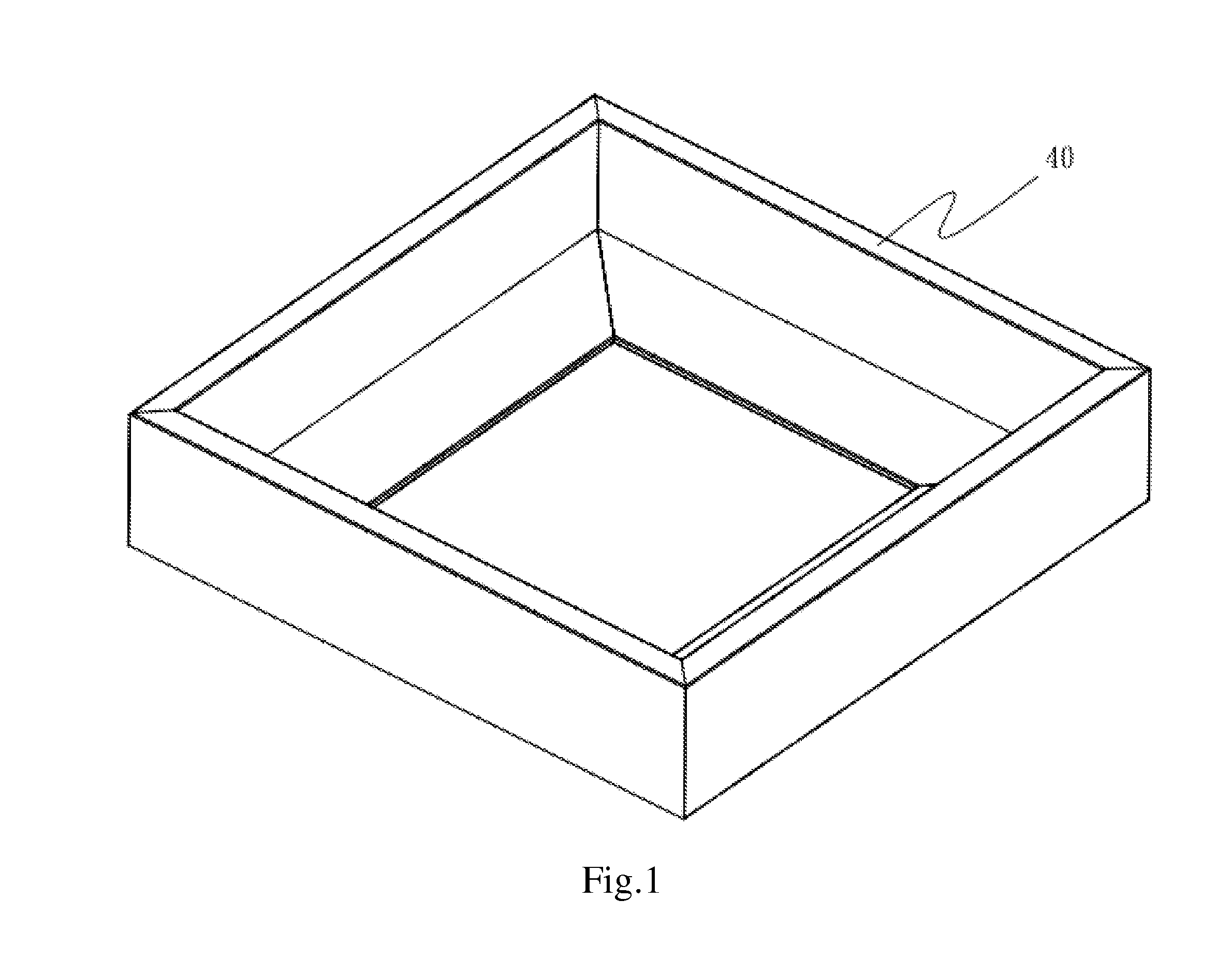
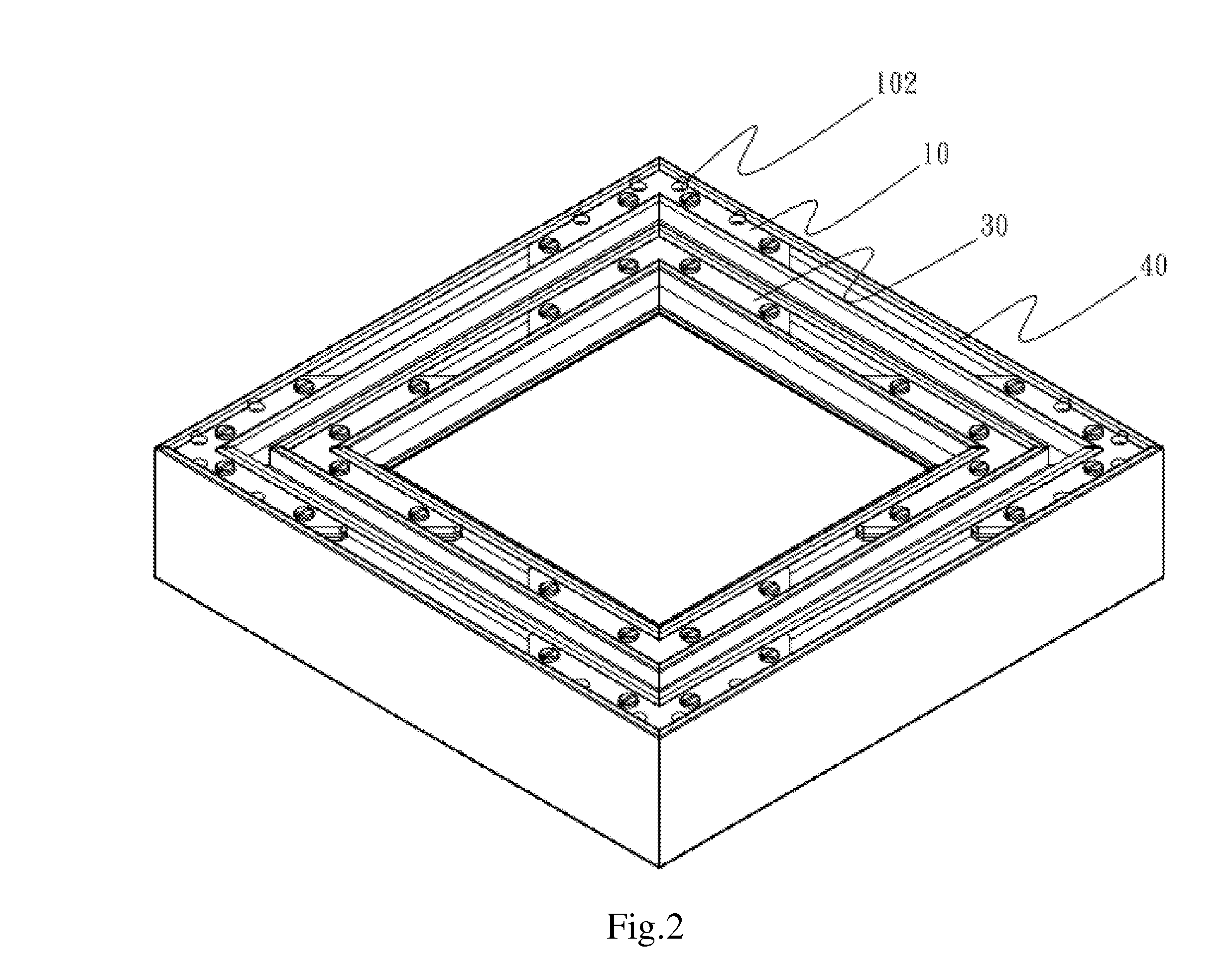
The present invention provides a frame that can connect segments tightly together and make them appear in flush with each other, which solves the issue of prior art frames where segments may be uneven in height. The frame is also sturdier and has a better appearance. This is achieved through the use of multiple inner retaining units that allow for a tight connection between neighboring segments, resulting in a more streamlined and visually appealing frame.

Problems solved by technology

In particular, regarding photo and picture frames made of metal, their segments are not easily tightened together and are often not in flush with each other; some of them may become loose and fall apart easily.
This adversely affects the appearance and utility of the frame.
These aluminum-made frames have many disadvantages: junctions between the segments may become loose; cracks may form between the segments; areas near fasteners on a segment may deform.

Method used


Image

  • Frame with segments that are flush with each other
  • Frame with segments that are flush with each other
  • Frame with segments that are flush with each other

Examples


second embodiment

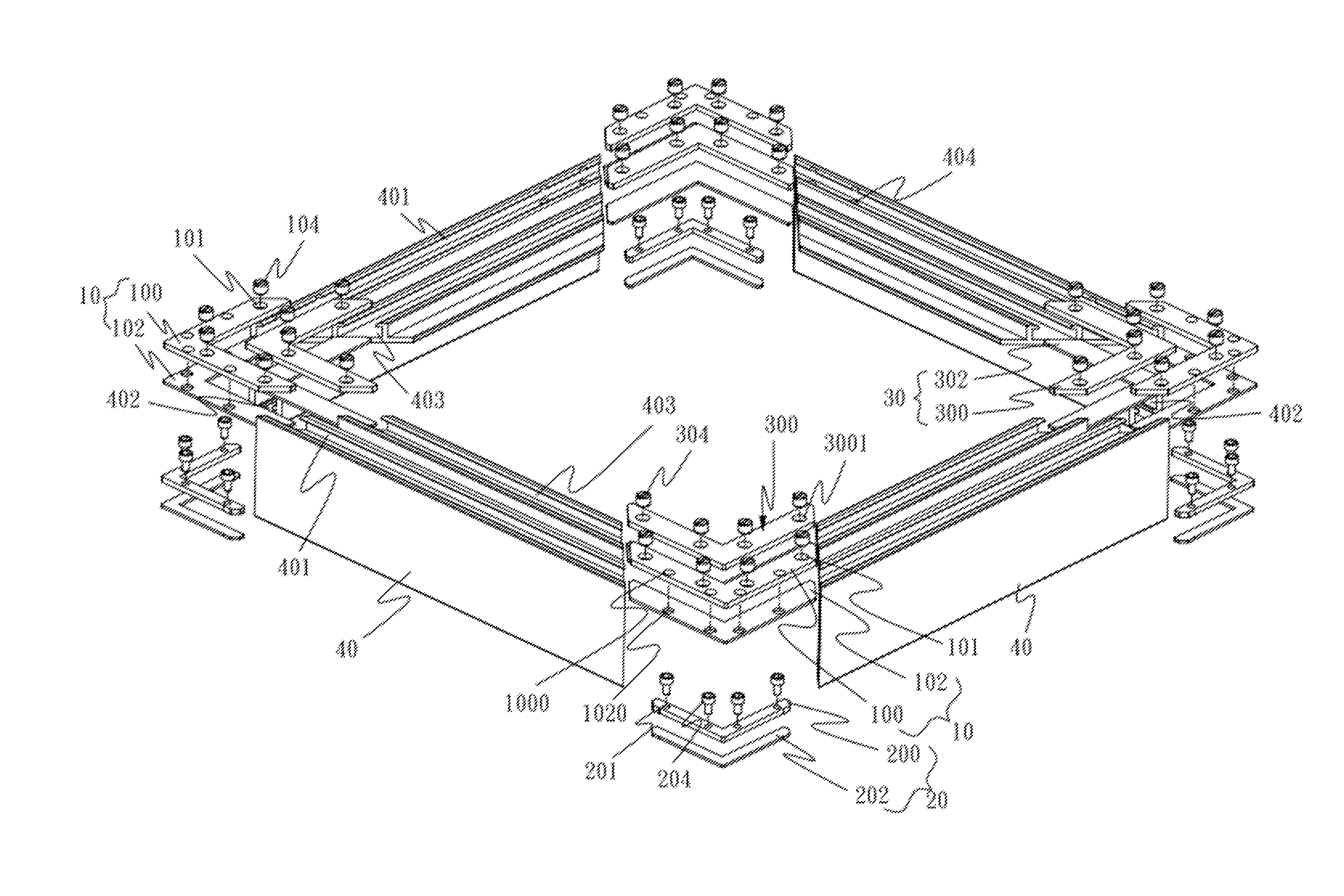
[0041]Because in the second embodiment, the frame is rectangular, either end of each segment has a 45-degree shape. Also, ends of the auxiliary upper retaining pieces 300 and auxiliary lower retaining pieces 302 have the same 45-degree shape. Length of either arm of each the auxiliary upper retaining piece 300 or each auxiliary lower retaining piece 302 is not greater than that of each segment 40. Width of either arm of each the auxiliary upper retaining piece 300 or each auxiliary lower retaining piece 302 is not greater than that of the auxiliary connective unit 403. Therefore, each the auxiliary upper retaining piece 300 and each auxiliary lower retaining piece 302 may be installed inside the corresponding auxiliary connective unit 403 so as to connect the segments 40 together.

[0042]In assembly, with each auxiliary upper retaining piece 300 aligned with the corresponding auxiliary lower retaining piece 302, as we use a tool to screw an auxiliary threaded fastener 304 into the cor...

third embodiment

[0043]In the third embodiment, there are no outer lower retaining pieces 102, inner lower retaining pieces 202 and auxiliary lower retaining pieces 302. Instead, each outer threaded fastener 104 presses against the bottom of the outer connective slot 401; each inner threaded fastener 204 presses against the bottom of the inner connective slot 402; each auxiliary threaded fastener 304 presses against the bottom of the auxiliary connective slot 403. However, forces so directly exerted are more uneven and may cause damages to the bottom of the outer connective slot 401, inner connective slot 402 and auxiliary connective slot 403. Therefore, it is preferred to provide the outer lower retaining pieces 102, inner lower retaining pieces 202 and auxiliary lower retaining pieces 302.

[0044]The frame of the present invention has the following two advantages:[0045](1) A plurality of outer retaining units 10 enable each pair of neighboring segments 40 to be tightly connected.[0046](2) A pluralit...


PUM


Abstract

A frame with segments that are in flush with each other is disclosed. The frame of the present invention comprises a plurality of segments, a plurality of outer retaining units and a plurality of inner retaining units. The segments are connected together to form a frame. Each outer retaining unit is disposed on the rear outer side of the juncture of each pair of neighboring segments. Each inner retaining unit is disposed on the rear inner side of the juncture of each pair of neighboring segments. In this manner, each pair of neighboring segments may be tightly joined together and the segments of the frame may be in flush with each other.

Description

CROSS-REFERENCE TO RELATED APPLICATION[0001]The present application claims priority from Taiwan Patent Application No. 104210993, filed on Jul. 8, 2015, which are hereby incorporated by reference in their entirety.BACKGROUND OF THE INVENTION[0002]1. Field of the Invention[0003]The invention generally relates to a frame. More particularly, the invention relates to a frame formed by segments that are in flush with each other.[0004]2. Description of the Prior Art[0005]Frames may be used as photo frames, picture frames, door frames, window frames, etc. Photo and picture frames are used mainly for embellishment; they may be used to enable photos and pictures to be easier to carry around; sometimes, they are used to protect photos and pictures; they may even be used for the decorative purpose like a piece of furniture. Photo and picture frames may be made of wood, plastic, metal or glass. A rectangular photo or picture frame comprises four segments; a hexagonal picture frame comprises six...

Claims


Application Information

Patent Timeline
IPC IPC(8): F16B7/18A47G1/06E06B3/08E06B1/36E06B1/52
CPCE06B3/968E06B3/9725F16B7/187E06B1/36E06B3/972E06B3/08A47G1/06E06B3/9682E06B1/52E06B3/9645E06B3/9688
Inventor OU, MING-LANG
Owner FRAME ART CO LTD
Learn More