
Piston ring configured to reduce friction

a technology of piston rings and rings, applied in the field of piston rings, can solve the problems of friction loss, friction loss, friction loss of lubricated sliding contacts, etc., and achieve the effect of reducing friction loss, reducing friction loss, and improving friction loss

Inactive Publication Date: 2017-01-12
FORD GLOBAL TECH LLC
View PDF0 Cites 3 Cited by
  • Summary
  • Abstract
  • Description
  • Claims
  • Application Information

AI Technical Summary

Benefits of technology

The technical effects of this patent text are that certain features are described in relation to only one or several aspects or arrangements of the disclosure to avoid unnecessary duplication of effort and repetition of text. However, it is to be understood that features described in relation to any aspect or arrangement of the disclosure may also be used with any other aspect or arrangement of the disclosure.

Problems solved by technology

Lubricated sliding contacts, such as between the piston rings of a piston and an inner surface of the cylinder bore, have frictional losses due to the shear forces generated in the lubricant, contact between surface asperities, and boundary contacts caused by additives in the lubricant.
However, it is difficult to maintain operation at the minimum point on the Stribeck curve across the full piston stroke as a result of the low relative speed between the piston and the cylinder at the extremes of the range of movement of the piston.

Method used


Image

  • Piston ring configured to reduce friction
  • Piston ring configured to reduce friction
  • Piston ring configured to reduce friction

Examples


Embodiment Construction

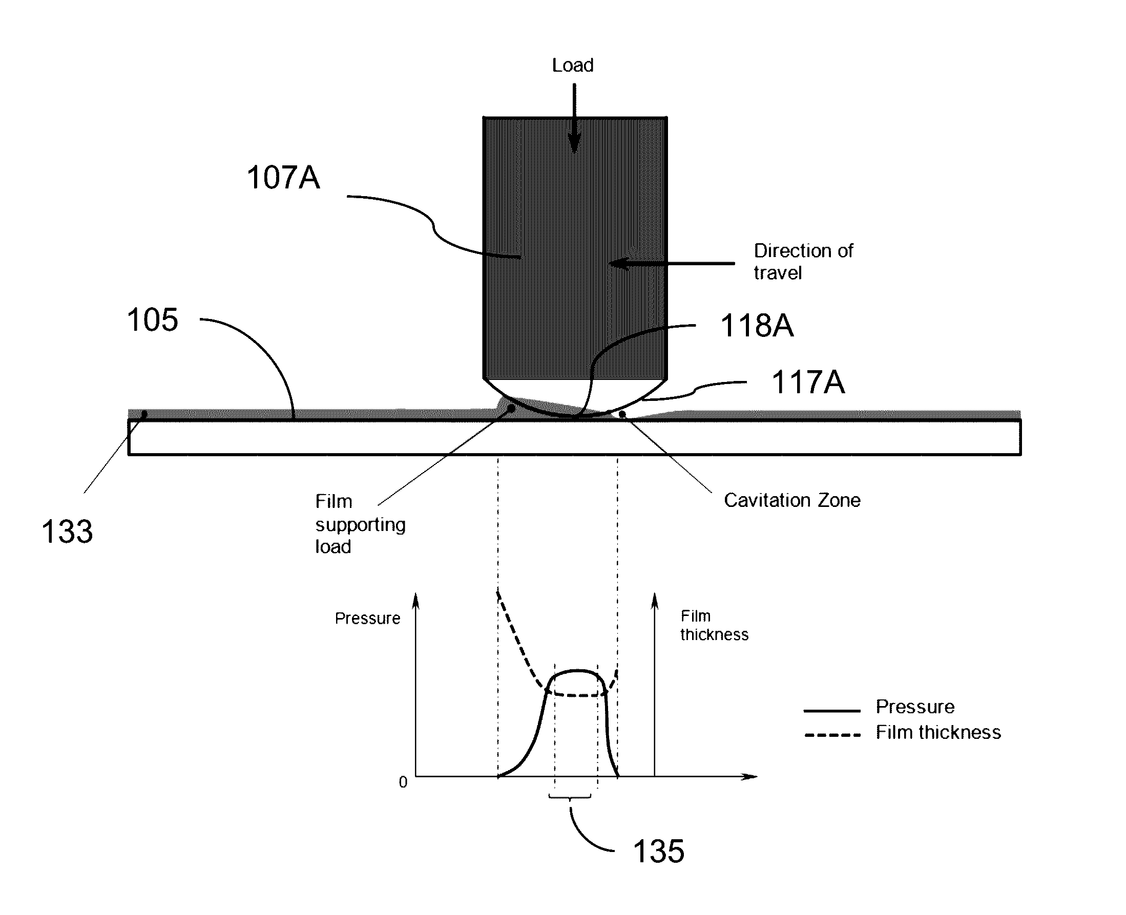
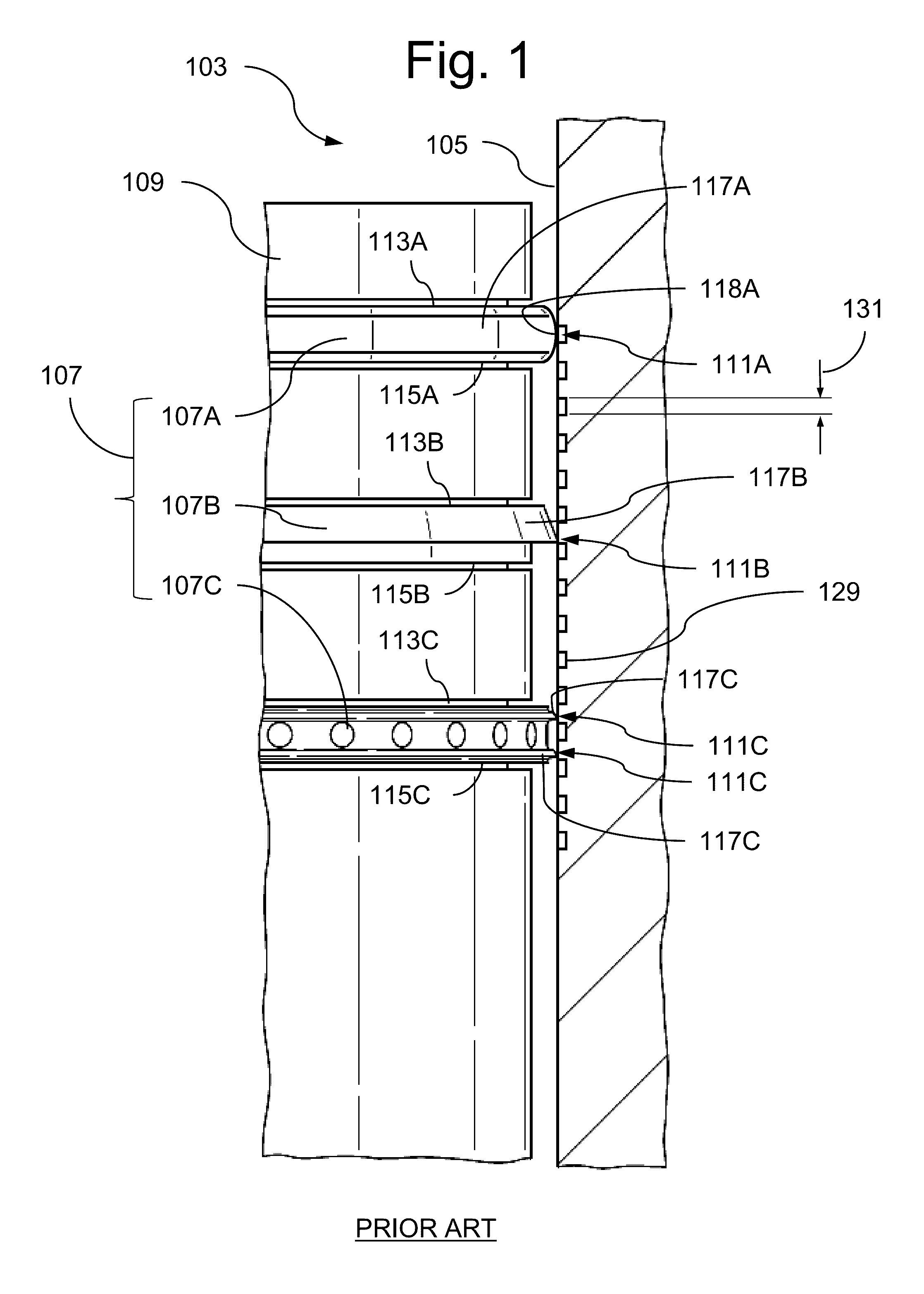
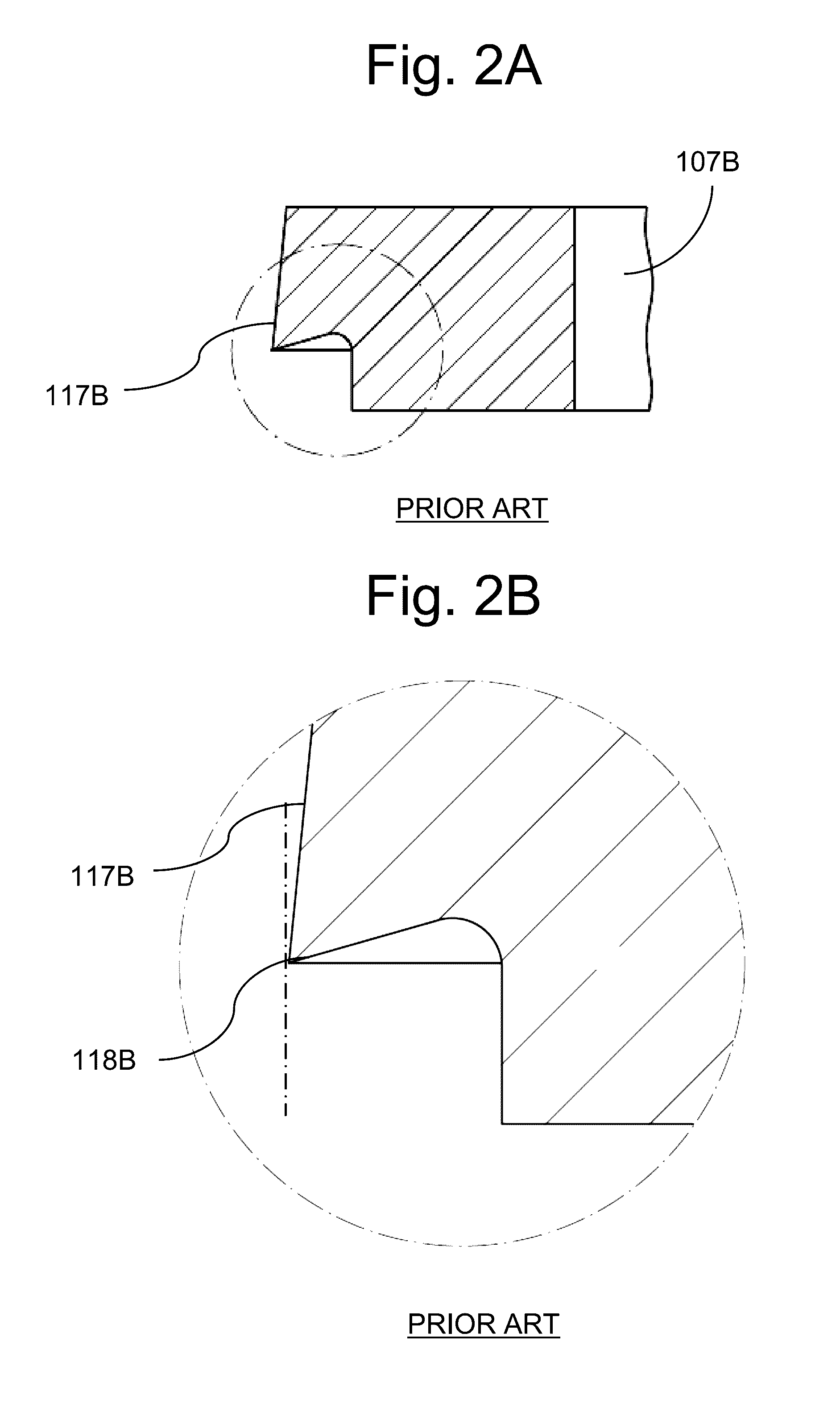
[0039]FIG. 1 shows a simplified cross-section of a cylinder 103 of an engine. The engine may be any type of engine, for example a single overhead camshaft (SOHC) engine, a double overhead camshaft (DOHC) engine, an overhead valve (OHV) engine, or other appropriate type of engine. The engine may comprise any appropriate number of cylinders 103, for example the engine may be a three-cylinder engine, a six-cylinder engine or an eight-cylinder engine. The cylinders 103 may be arranged in an appropriate configuration, such as in-line, horizontally opposed or V-form.

[0040]Each of the cylinders 103 comprises an inner surface 105 configured to engage the piston rings 107 of an engine piston 109. The inner surface 105 may be an inner surface of a cylinder bore formed directly into a cylinder block of the engine. Alternatively, the inner surface 105 may be an inner surface of a cylinder liner that is assembled into the cylinder block.

[0041]During operation of the engine, each of the pistons 1...


PUM


Abstract

A piston ring for a piston, the piston ring having a circumferential surface configured to engage an inner surface of a cylinder, the inner surface having at least one recess indented into the inner surface, the engagement of the circumferential surface of the piston ring with the inner surface of the cylinder defining a contact zone therebetween, wherein the circumferential surface of the piston ring is configured such that the ratio of the dimension of the contact zone the direction of travel of the piston to the dimension of the recess in the direction of travel of the piston is in the range of approximately 5:1 to 5:3.

Description

CROSS REFERENCE TO RELATED APPLICATION[0001]This application claims priority to Great Britain Patent Application No. 1512125.4, filed Jul. 10, 2015, the entire contents of which are hereby incorporated by reference for all purposes.FIELD[0002]This disclosure relates to a piston ring that is configured to reduce the friction between the piston ring a cylinder bore, and in particular relates to a piston ring having a circumferential surface configured to trap lubricant in one or more recesses in a cylinder bore.INTRODUCTION[0003]An internal combustion engine typically has one or more reciprocating pistons which are lubricated to reduce the friction as the piston slides within a cylinder bore. Lubricated sliding contacts, such as between the piston rings of a piston and an inner surface of the cylinder bore, have frictional losses due to the shear forces generated in the lubricant, contact between surface asperities, and boundary contacts caused by additives in the lubricant.[0004]It i...

Claims


Application Information

Patent Timeline
IPC IPC(8): F16J9/12
CPCF16J9/12F16J9/206F16J9/20F16J10/04F16J9/00
Inventor PEGG, IAN GRAHAM
Owner FORD GLOBAL TECH LLC
Learn More