Spool brake device for dual-bearing reel

Active Publication Date: 2017-01-19
SHIMANO INC
View PDF0 Cites 2 Cited by
  • Summary
  • Abstract
  • Description
  • Claims
  • Application Information

AI Technical Summary

Benefits of technology

The spool brake device for a fishing reel described in the patent text uses the rotational acceleration of the spool to effectively brake it. This device predicts the starting time of the brake and ensures that it is reliable. By monitoring the reduction in rotational acceleration, the device can accurately set the prediction starting time. The brake starting time can also be set based on the time series data of rotational acceleration. Overall, the device provides an effective way to brake the spool and improve the performance of the fishing reel.

Problems solved by technology

However, the rotational velocity of the spool often becomes unstable in a velocity range around the maximum value.
Hence, it is difficult to accurately detect the maximum value of the rotational velocity of the spool and the timing that the rotational velocity is maximized.
In other words, there has been a drawback of difficulty in appropriately braking the spool.

Method used


Image

  • Spool brake device for dual-bearing reel
  • Spool brake device for dual-bearing reel
  • Spool brake device for dual-bearing reel

Examples


Embodiment Construction

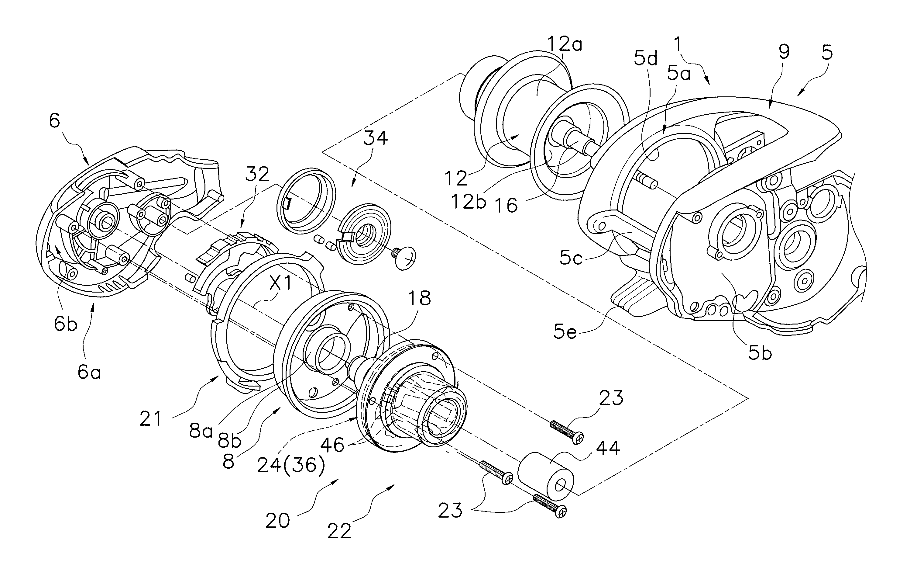
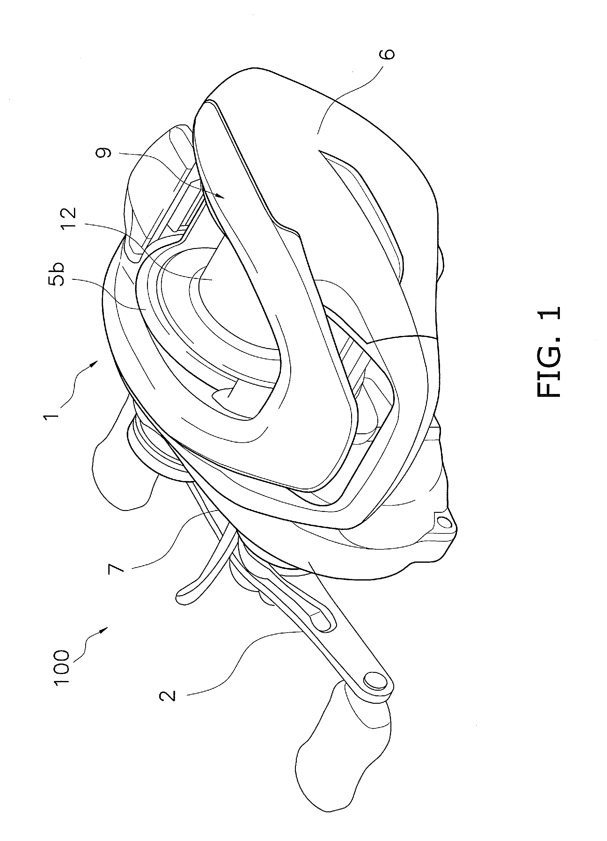
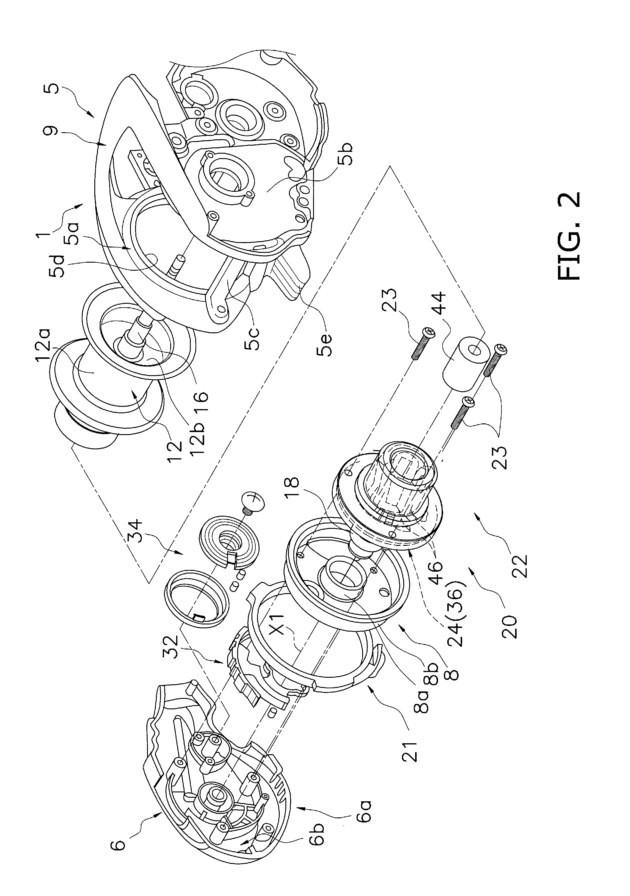
[0029]As shown in FIGS. 1 and 2, a dual-bearing reel 100 employing a preferred embodiment of the present disclosure includes a reel unit 1, a handle 2, a spool 12 and a spool brake mechanism 20 (see FIG. 2) configured to electrically brake the spool 12. The spool brake mechanism 20 is an exemplary spool brake device for the dual-bearing reel 100. It should be noted that in FIG. 2, reference sign X1 indicates the rotational axis of the spool 12.

[0030]The reel unit 1 includes a frame 5, a first side cover 6 and a second side cover 7. The frame 5 is an integrally formed component. The first side cover 6 is disposed laterally to the frame 5 on the opposite side of the handle 2. The second side cover 7 is disposed laterally to the frame 5 on the same side as the handle 2.

[0031]As shown in FIG. 2, the frame 5 includes a first side plate 5a, a second side plate 5b, a plurality of coupling portions 5c and a thumb rest 9. The first side plate 5a is disposed on the opposite side of the handle...


PUM


Abstract

A spool brake device for a fishing reel includes a velocity detector, a spool controller and a spool brake. The velocity detector is configured to detect a rotational velocity of a spool. The spool controller includes an acceleration generator, an acceleration determiner and a brake time predictor. The accelerator generator is configured to generate time-series data of a rotational acceleration based on the rotational velocity. The acceleration determiner is configured to determine whether the rotational acceleration has satisfied a predetermined condition based on the time-series data of the rotational acceleration. The brake time predictor is configured to set a prediction starting time based on a point of time at which the rotational acceleration has satisfied the predetermined condition and to predict a brake starting time of the spool based on the prediction starting time. The spool brake is configured to start braking the spool at the brake starting time.

Description

CROSS-REFERENCE TO RELATED APPLICATIONS[0001]This application claims priority to Japanese Patent Application No. 2015-139861, filed on Jul. 13, 2015, the entirety of which is hereby incorporated by reference in its entirety.BACKGROUND[0002]Technical Field[0003]The present disclosure relates to a spool brake device for a fishing reel.[0004]Background Art[0005]To prevent an occurrence of a backlash in casting, some dual-bearing reels are provided with a spool brake device for braking a spool (Japan Laid-open Patent Application Publication No. H11-332436). This type of spool brake device includes, for instance, a spool brake and a rotational velocity detection device (velocity detector). The spool brake includes a magnet mounted to a spool and one or more coils mounted to a reel unit. The rotational velocity detection device is configured to detect the rotational velocity of the spool. In the spool brake device, the rotational velocity detection device monitors the rotational velocity ...

Claims


Application Information

Patent Timeline
IPC IPC(8): A01K89/0155
CPCA01K89/01555A01K89/033A01K89/02A01K89/015
Inventor KOMEMUSHI, TAKASHINIITSUMA, AKIRAISHIKAWA, YUICHIRO
Owner SHIMANO INC
Why Eureka
Try Eureka