Method for controlling a hybrid driveline

a technology of hybrid powertrain and driveline, which is applied in the direction of electric propulsion mounting, transportation and packaging, gearing, etc., can solve the problem of superfluous energy storage devices, and achieve the effect of convenient shifting

Active Publication Date: 2017-01-19
SCANIA CV AB
View PDF0 Cites 13 Cited by
  • Summary
  • Abstract
  • Description
  • Claims
  • Application Information

AI Technical Summary

Benefits of technology

[0020]In some applications, it may be advantageous not to equip the vehicle with an energy storage device. Energy storage devices are costly, have a considerable weight and are bulky. Even if the vehicle is, or will be, equipped with an energy storage device, there may arise situations wherein the energy storage device is insufficient, such as when there are operating problems, or in special operating conditions, such as extreme temperatures. Furthermore, energy storage devices may be taken out of operation during a certain production stage, or in connection with repair of the vehicle and the energy storage device. In that case, it is an advantage if the vehicle may be used with as normal a function as possible. By leading electric power from the first electrical machine to the second electrical machine via a switch, no electric power will be led to and from the energy storage device. Thus, conditions are created for an increased life of the energy storage device.
[0023]According to one embodiment of the invention, it is ensured that the first planetary gear's rotatable components are disconnected from each other, and that the second planetary gear's rotatable components are disconnected from each other. Accordingly, an efficient moving off of the vehicle, which is equipped with the hybrid powertrain, is facilitated. The vehicle is moved off from a standstill state of the vehicle, or from a state where the vehicle is travelling at a low speed. When the vehicle's driver moves a speed control to a desired state, the electrical machines are controlled in such a way that a torque is generated in the output shaft. The vehicle will then accelerate to the desired speed with the help of the energy from the combustion engine. While moving off the vehicle, the planetary gears' rotatable components are disconnected from each other and a suitable gear is engaged in the gearbox. According to this embodiment, the first electrical machine controls the voltage between the electrical machines, while simultaneously the second electrical machine is controlled to emit a predetermined torque.
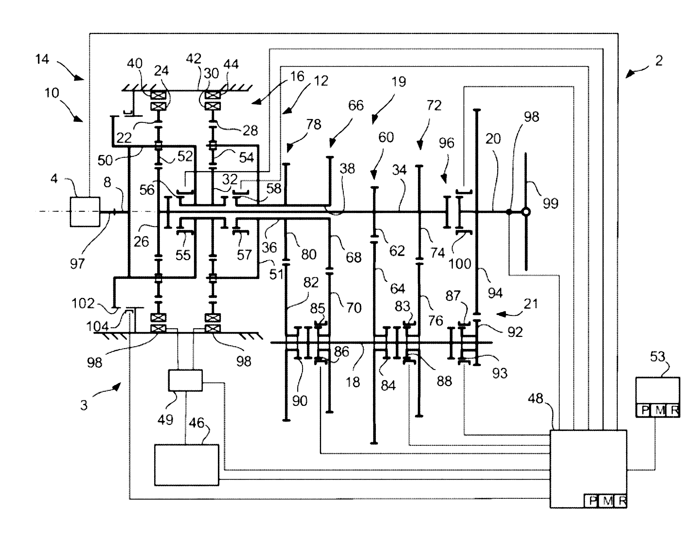
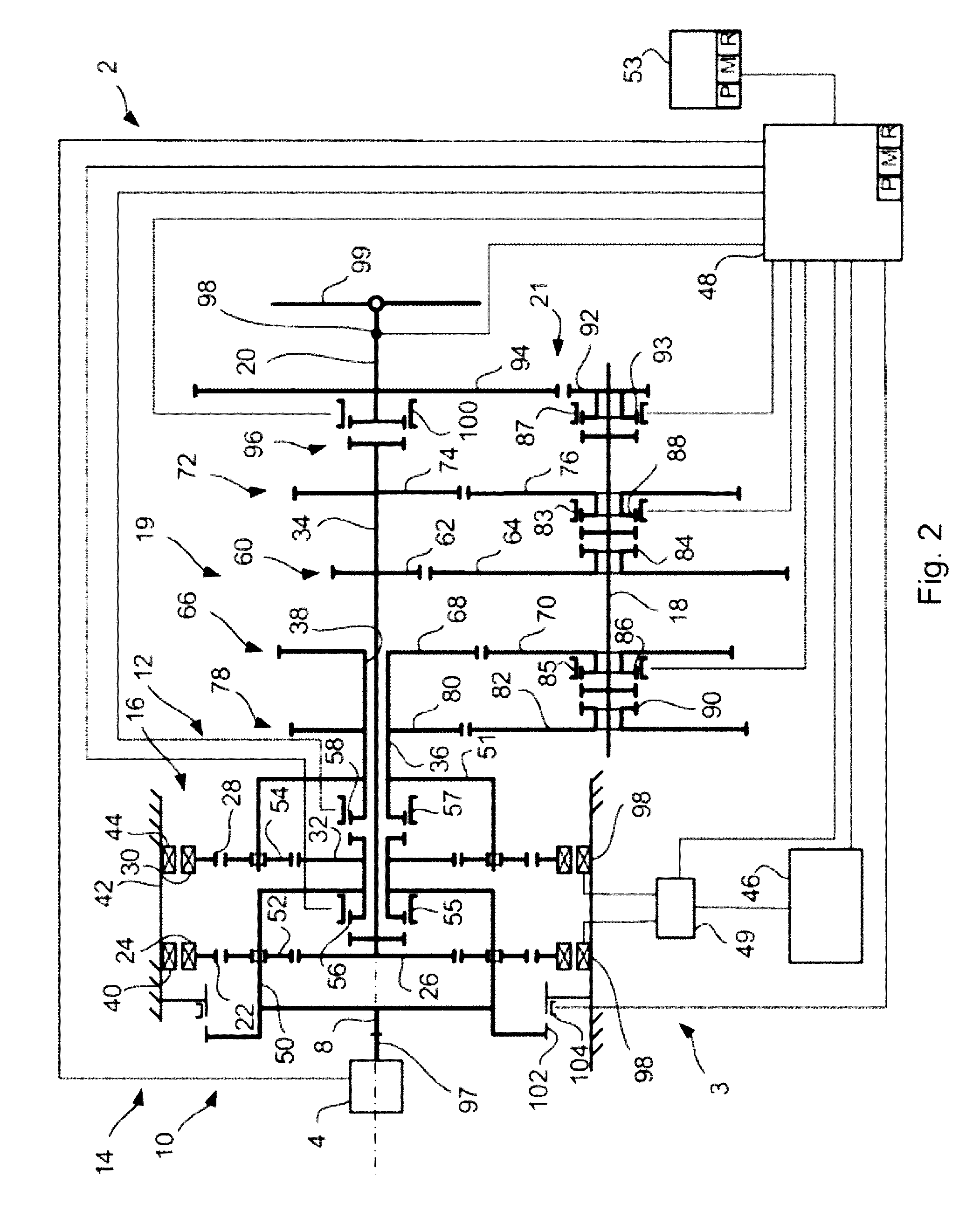
[0028]The gearbox may be equipped with a number of gear pairs, comprising cogwheels that may be mechanically locked with and released from a countershaft. Thus, a number of fixed gear steps is obtained, which may be shifted without torque interruption. The cogwheels that may be locked on the countershaft also result in a compact construction with high reliability and high dependability. Alternatively, pinion gears in the gear pairs may be arranged to be lockable and disconnectable on the first and / or second main shaft.
[0030]A first and second coupling device is arranged between the planetary wheel carrier and the sun wheel of the respective planetary gears. The task of the coupling devices is to lock the respective planetary wheel carriers with the sun wheel. When the planetary wheel carrier and the sun wheel are connected with each other, the power from the combustion engine will pass through the planetary wheel carrier, the coupling device, the sun wheel and further along to the gearbox, which entails that the planetary wheels do not absorb any torque. This entails that the dimension of the planetary wheels may be adapted only to the electrical machine's torque instead of the combustion engine's torque, which in turn means the planetary wheels may be designed with smaller dimensions. Thus, a drive arrangement according to the invention is obtained, which has a compact construction, a low weight and a low manufacturing cost.
[0031]The coupling devices and the locking mechanisms preferably comprise an annular sleeve, which is shifted axially between a connected and a disconnected state. The sleeve encloses, substantially concentrically, the gearbox's rotating components and is moved between the connected and disconnected state with a power element. Thus, a compact construction is obtained, with a low weight and a low manufacturing cost.
[0034]Torque balance relates to a state where a torque acts on an internal ring gear arranged in the planetary gear, representing the product of the torque acting on the planetary wheel carrier of the planetary gear and the gear ratio of the planetary gear, while simultaneously a torque acts on the planetary gear's sun wheel, representing the product of the torque acting on the planetary wheel carrier and (1—the planetary gear's gear ratio). In the event two of the planetary gear's component parts, i.e. the sun wheel, the internal ring gear or planetary wheel carriers, are connected with a coupling device, this coupling device does not transfer any torque between the planetary gear's parts when torque balance prevails. Accordingly, the coupling device may easily be shifted and the planetary gear's component parts be disconnected.

Problems solved by technology

Thus, an energy storage device becomes superfluous.

Method used


Image

  • Method for controlling a hybrid driveline
  • Method for controlling a hybrid driveline
  • Method for controlling a hybrid driveline

Examples


Embodiment Construction

[0040]FIG. 1 shows a schematic side view of a vehicle 1, comprising a gearbox 2 and a combustion engine 4, which are comprised in a hybrid powertrain 3. The combustion engine 4 is connected to the gearbox 2, and the gearbox 2 is further connected to the driving wheels 6 of the vehicle 1 via a propeller shaft 9. The driving wheels 6 are equipped with brake devices 7 to brake the vehicle 1.

[0041]FIG. 2 shows a schematic side view of a hybrid powertrain 3 with a gearbox 2, comprising an input shaft 8, a first and a second planetary gear 10 and 12, respectively, a first and a second electrical machine 14 and 16, respectively, a countershaft 18 and an output shaft 20. The hybrid powertrain comprises a combustion engine 4, connected to the gearbox 2. The combustion engine 4 is connected with the gearbox 2 via the input shaft 8 of the gearbox. The combustion engine has an output shaft 97. The output shaft 97 of the combustion engine 4 is connected to the input shaft of the gearbox 2. The f...


PUM


Abstract

A method is provided for controlling a hybrid powertrain, comprising a combustion engine; a gearbox with input and output shafts; a first planetary gear connected to the input; a second planetary gear connected to the first planetary gear; first and second electrical machines capable of operating each other and respectively connected to the first planetary gear and to the second planetary gear; one gear pair connected with the first planetary gear and the output shaft; and one gear pair connected with the second planetary gear and the output shaft. The method comprising, while the combustion engine is operating: ensuring that gears are engaged in the one gear pair connected with the first planetary gear and the one gear pair connected with the second planetary gear, and activating the first and second electrical machines so that total emitted electrical power is zero and a torque is generated in the output shaft.

Description

CROSS-REFERENCE TO RELATED REFERENCE(S)[0001]This application is a national stage application (filed under 35 §U.S.C. 371) of PCT / SE15 / 050301, filed Mar. 17, 2015 of the same title, which, in turn claims priority to Swedish Application No. 1450327-0, filed Mar. 20, 2014 of the same title; the contents of each of which are hereby incorporated by reference.FIELD OF THE INVENTION[0002]The present invention relates to a method, vehicle and computer program product to control a hybrid powertrain.BACKGROUND OF THE INVENTION[0003]Hybrid vehicles may be driven by a primary engine, which may be a combustion engine, and a secondary engine, which may be an electrical machine. The electrical machine is equipped with at least one energy storage device, such as an electro-chemical energy storage device, for storage of electric power and control equipment to control the flow of electric power between the energy storage device and the electrical machine. The electrical machine may thus alternately ...

Claims


Application Information

Patent Timeline
Patent Type & Authority Applications(United States)
IPC IPC(8): B60W20/30B60W10/08B60W10/02F16H37/04B60K6/365B60K6/442F16H3/72B60W10/06B60W10/115
CPCB60W20/30B60W10/06B60W10/08B60W10/02B60W10/115B60K6/365Y10S903/919F16H3/728F16H37/042B60Y2200/92B60Y2300/70Y10S903/945Y10S903/911B60K6/442B60K6/445B60K6/547B60W20/00F16H2003/008F16H37/046F16H3/006F16H2037/102B60W20/40Y02T10/62B60K6/40B60K1/02B60W10/113B60W20/10B60K6/34B60W20/50F16H3/725F16H3/08F16H3/0915
Inventor BJORKMAN, MATHIASPETTERSSON, NIKLASLINDSTROM, JOHANBERGQUIST, MIKAEL
Owner SCANIA CV AB
Why Eureka
Try Eureka