High voltage bushing, a method of cooling a conductor thereof, and an electric power distribution system comprising such a bushing

a technology of high voltage bushings and conductors, which is applied in the direction of power cables, cables, electrical apparatus construction details, etc., can solve the problems of increasing losses, increasing weight, and so as to increase the level of electric current without increasing the load on the conductor thereof too much

Inactive Publication Date: 2011-06-14
ABB POWER GRIDS SWITZERLAND AG +1
View PDF8 Cites 4 Cited by
  • Summary
  • Abstract
  • Description
  • Claims
  • Application Information

AI Technical Summary

Benefits of technology

[0009]It is an object of the present invention to provide for a sufficient cooling of an electric high voltage bushing without increasing the load on the conductor thereof too much. It is also an object of the invention to provide a bushing with a capability of conducting increased levels of electric current without being overheated, and without adding so much weight to the bushing that its ability of absorbing elevated mechanical loads, such as those caused by seismic disturbances, becomes insufficient.
[0010]The object of the invention is achieved by means of initially defined bushing, characterized in that said cooling means comprises at least one cooling element extending along a fraction of the length of said conductor and in thermal connection with said conductor. Thereby, local cooling of regions of the conductor that are more prone to heating can be performed, without the necessity of filling the whole length of any central channel or other longitudinal channel of the bushing with a liquid that will add a considerable weight to be carried by the conductor.
[0015]According to a preferred embodiment, said cooling element comprises a tubular body. Preferably the tubular body has end walls, preferably integrated with the mantle, thereby defining a closed space through which a cooling medium may be circulated. Checking the tightness of such a body will be a relatively easy operation, and the risk of having leakages of cooling medium out of the element and into the conductor channel will be reduced. This design also promotes a relatively light-weight, thin-walled element that does not in itself add so much weight to carried by the conductor.
[0019]According to a preferred embodiment, each of said first and second conduits is formed by a hose or pipe separate from the conductor and extending inside said channel of the latter. The volume of the channels defined by said conduits inside said channel should be substantially less than the volume of the channel. Thereby, the weight gain compared to the case in which the cooling medium is permitted to flow through and fill the whole conductor channel is considerable, and only as much cooling medium as needed for the purpose of performing the cooling of the cooling elements may be used. In other words, the channel of the conductor may be optimized with regard to the functional requirements of the conductor, while the volume of the conduits for supplying the cooling medium the cooling element or elements may be optimized with regard to the needed cooling effect, and the use of excessive amounts of cooling medium, increasing the load on the conductor, is avoided.

Problems solved by technology

It is a design challenge to make the conductor able of coping with elevated mechanical loads, such as those appearing in connection to, for example, an earth quake or any other seismic phenomena, and still being able of carrying high voltages.
However, if the electric current is increased, which will most probably be the case in future applications, there will be spots along the length of the conductor where the cooling thereof by the surrounding gas or any other surrounding media is insufficient, thereby resulting in increased losses.
However, such a solution will add considerable weight, caused by the liquid, to the bushing.
In some bushings this is fully acceptable, but in other bushings, such as those in which there is no supporting condenser, it will be unacceptable, since it will make the load on the conductor to large.
Accordingly, the conductor will become less able of standing the test of seismic abnormalities.

Method used


Image

  • High voltage bushing, a method of cooling a conductor thereof, and an electric power distribution system comprising such a bushing
  • High voltage bushing, a method of cooling a conductor thereof, and an electric power distribution system comprising such a bushing
  • High voltage bushing, a method of cooling a conductor thereof, and an electric power distribution system comprising such a bushing

Examples


Embodiment Construction

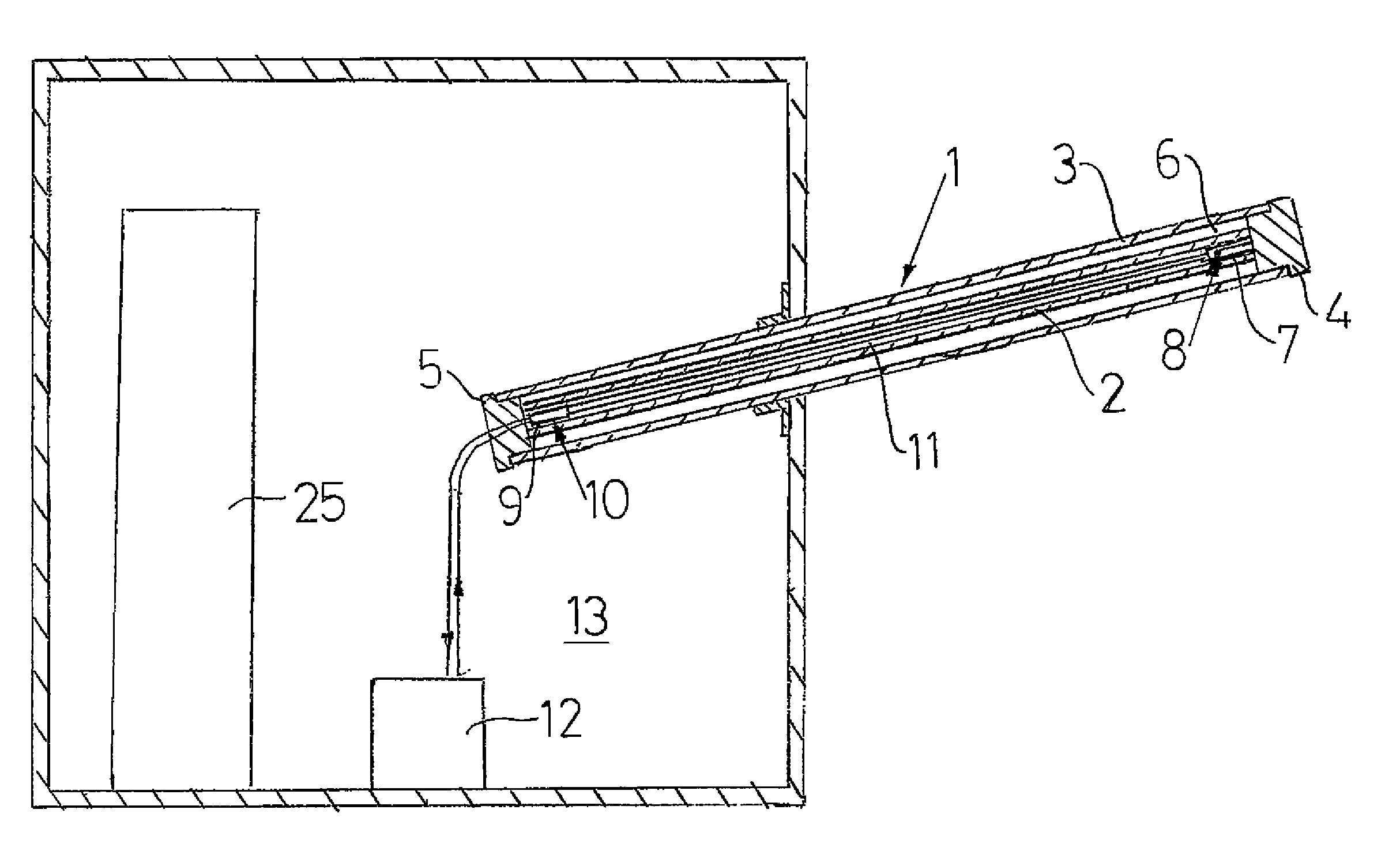
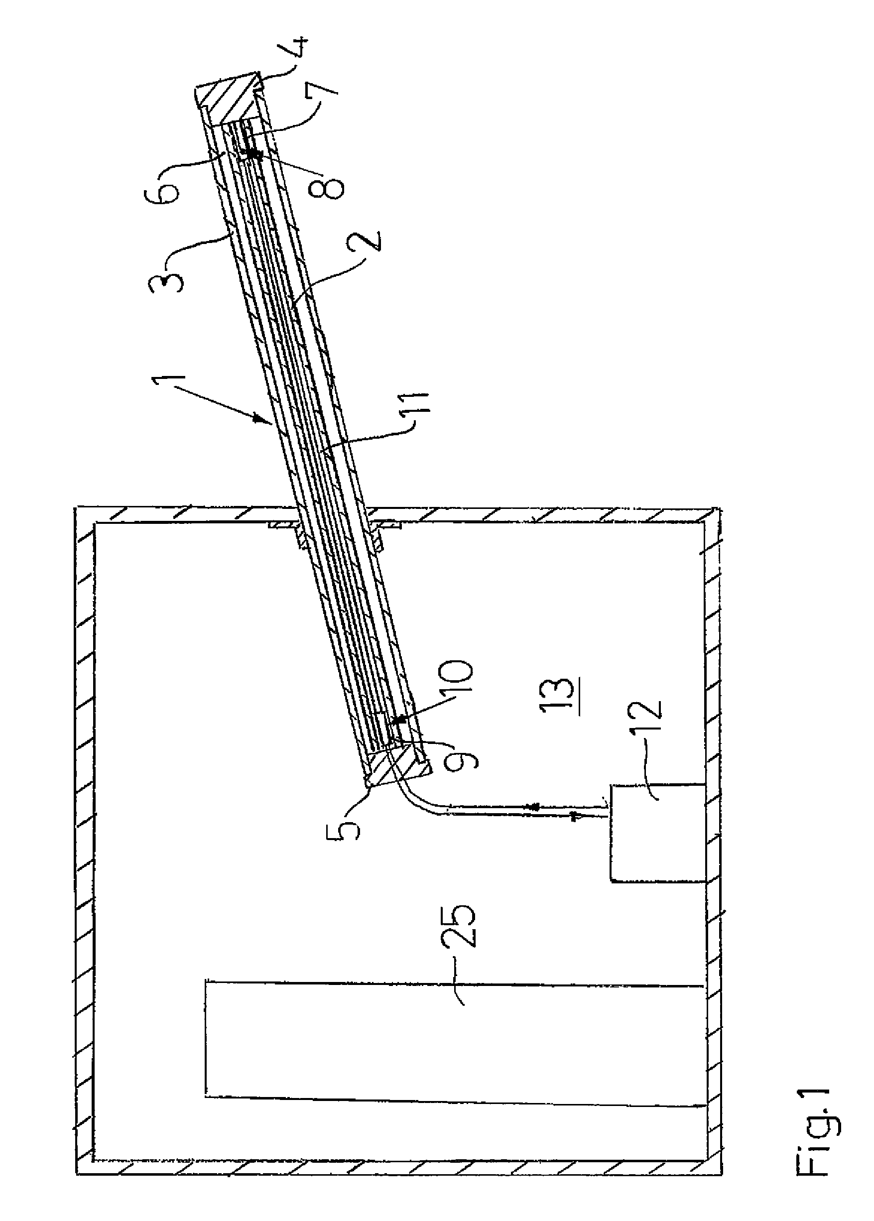
[0036]FIG. 1 shows a bushing 1 according to the invention. The bushing is an UHVDC wall bushing, which is a bushing adapted for use in power distribution systems operating with very high voltages, i.e. above 300 kV and even up to 800 kV (and the voltages will probably increase even further in the future). The bushing 1 is of a very long (in the range of 10-20 meters) and slender type, which in its operative position is supposed to extend in a direction other than vertical, and preferably also other than horizontal. Thereby, there will be certain requirements on the ability of the bushing 1 and individual parts thereof to carry its own weight and the bending forces induced by the latter, not only under normal circumstances but also under exceptional circumstances such as seismic disturbances. Therefore, the bushing 1 and separate parts thereof should have a rather high strength / weight ratio or stiffness / weight ratio.

[0037]The bushing 1 comprises an elongated tubular conductor 2 and a...


PUM


Abstract

A high voltage bushing including an elongated electric conductor, a tubular insulator surrounding the conductor, and cooling mechanism for cooling the conductor. The cooling mechanism includes at least one cooling element extending along a fraction of the length of the conductor and in thermal connection with the conductor.

Description

CROSS-REFERENCE TO RELATED APPLICATIONS[0001]The present application is a continuation of pending International patent application PCT / EP2008 / 067015 filed on Dec. 8, 2008, which designates the United States and claims priority from European patent application number 07123918.0 filed on Dec. 21, 2007, the content of which is incorporated herein by reference.FIELD OF THE INVENTION[0002]The present invention relates to a high voltage bushing comprising an elongated electric conductor, a tubular insulator surrounding said conductor, and cooling means for cooling said conductor.[0003]The invention also relates to a method of cooling a conductor of such a bushing, and an electric power distribution system comprising such a bushing.[0004]High voltage is referred to as voltages above 1 kV. However, the design of the bushing of the invention will contribute to making the latter particularly suitable for very high voltages, preferably from 300 kV and above.[0005]Typically, but not necessarily...

Claims


Application Information

Patent Timeline
Patent Type & Authority Patents(United States)
IPC IPC(8): H05K7/20
CPCH01B17/54
Inventor ERIKSSON, THOMAS
Owner ABB POWER GRIDS SWITZERLAND AG
Why Eureka
Try Eureka