Camshaft with Camshaft Adjuster

Inactive Publication Date: 2013-03-21
THYSSENKRUPP PRESTA TECCENTER AG
View PDF3 Cites 5 Cited by
  • Summary
  • Abstract
  • Description
  • Claims
  • Application Information

AI Technical Summary

Benefits of technology

[0014]In accordance with a further embodiment of the invention, the valve is also disposed in the interior of the camshaft tube and is connected thereto in a rotationally-fixed manner. Owing to the fact that the v

Problems solved by technology

WO 2009/009328 A1 have, inter alia, the disadvantage that virtually the entire interior of the camshaft tube is taken up either by the tubular connecting element (embodiment 1) or by the lengthened solenoid (embodiment 2) and thus cannot be used for the integration of further components (such as for example oil separating devices for purifying blow-by gas) or for other uses.
Therefore, further functional elements can no longer be integrated into the interior of the camshaft tube.
The tota

Method used


Image

  • Camshaft with Camshaft Adjuster
  • Camshaft with Camshaft Adjuster
  • Camshaft with Camshaft Adjuster

Examples


Embodiment Construction

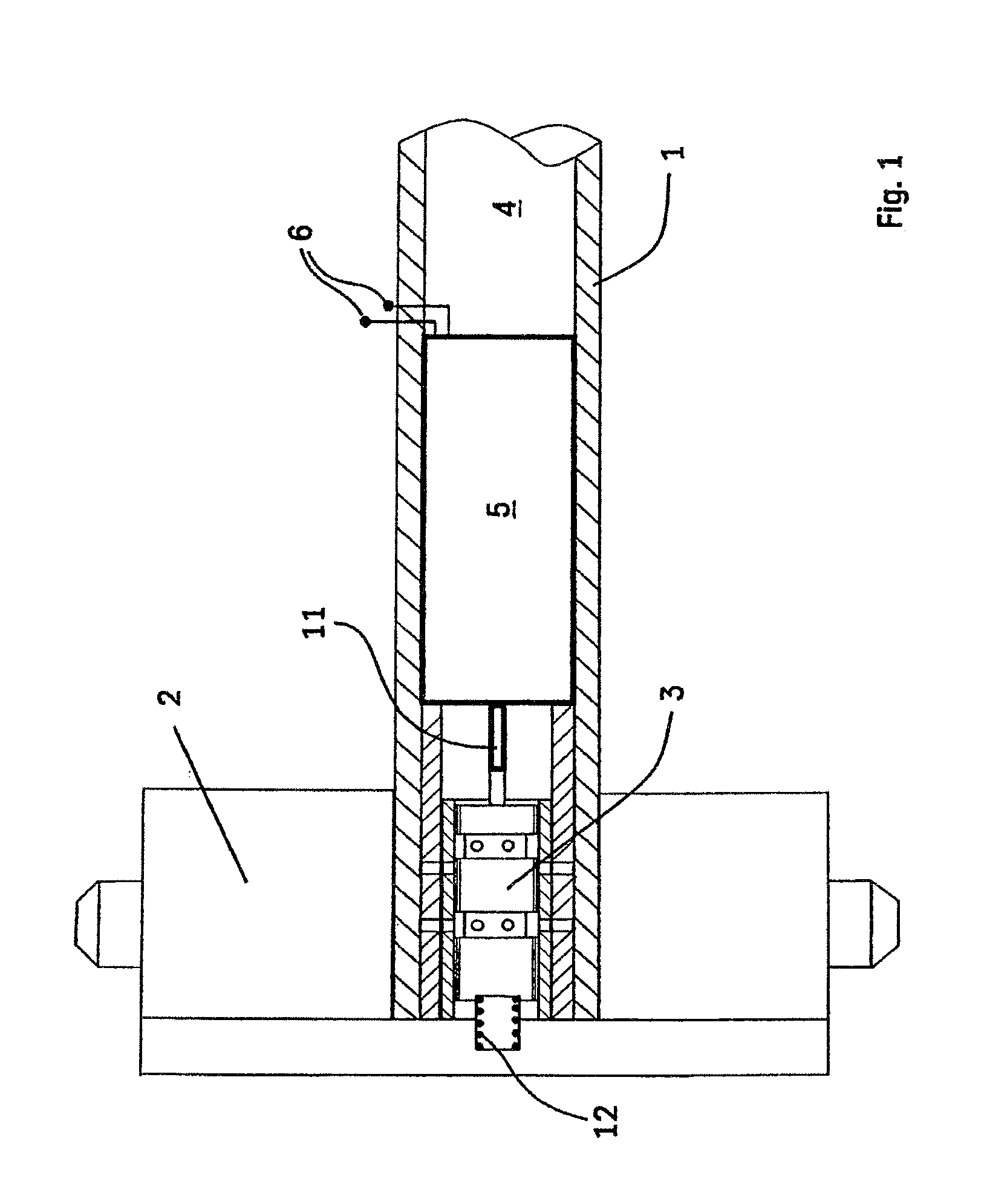
[0023]FIG. 1 shows an axial half-section of a camshaft in accordance with the invention. A hydraulic camshaft adjuster 2 is disposed on the end of the camshaft tube 1 on the left-hand side in FIG. 1 in a manner known per se. Such camshaft adjusters comprise drive elements that are connected directly or indirectly to the crankshaft of the internal combustion engine and are driven thereby. Furthermore, such known camshaft adjusters comprise adjusting elements that are connected to the camshaft tube 1 and can be rotated relative to the drive elements by hydraulic actuation in order to effect phase adjustment of the camshaft relative to the crankshaft.

[0024]Such known camshaft adjusters 2 are controlled via hydraulic valves. This means that the hydraulic fluid effecting the adjustment is fed to a hydraulic camshaft adjuster via a hydraulic valve in an manner required for the desired adjustment. The hydraulic fluid is used to rotate the part of the camshaft adjuster 2—connected to the ca...


PUM


Abstract

A camshaft for actuating the gas exchange valves of an internal combustion engine. The camshaft includes a camshaft tube, a hydraulic camshaft adjuster, a valve for controlling the hydraulic fluid supplied to the camshaft adjuster and an actuation device, arranged in the interior of the camshaft tube, for actuating the valve. The actuation device is secured against displacement in the axial direction. The camshaft is light-weight and functional elements in addition to the actuation device and optionally the valve can be integrated into the interior of the camshaft. It should furthermore be possible to arrange an oil or vacuum pump at the end of the camshaft opposite the camshaft adjuster, the pump being drivable by the camshaft. The actuation device is designed as an electromagnetic, piezoelectric or electrical actuator and is connected to the camshaft tube such that they rotate together.

Description

BACKGROUND AND SUMMARY OF THE INVENTION[0001]The invention relates to a camshaft for actuating the gas exchange valves of an internal combustion engine, having a camshaft tube, a hydraulic camshaft adjuster, a valve for controlling the hydraulic fluid supplied to the camshaft adjuster and an actuating device disposed in the interior of the camshaft tube for actuating the valve which is secured in the axial direction to prevent displacement.[0002]PCT International Publication No. WO 2009 / 009328 A1 discloses a camshaft having an actuating device formed as an electromagnet (solenoid) that does not rotate along with the camshaft tube when the camshaft rotates. The solenoid is disposed so as to always be fixed to the cylinder head, i.e., it is fixedly connected to the cylinder head of the engine. Two different embodiments are described, showing how the solenoid can be disposed in the interior of the camshaft. In accordance with a first embodiment, the solenoid is mounted via a bearing el...

Claims


Application Information

Patent Timeline
IPC IPC(8): F01L9/04F01L9/20
CPCF01L1/344F01L1/3442F01L2001/0475F01L2001/34426F01L9/04F01L2001/34433F01L2101/00F01L2820/041F01L2001/3443F01L2301/00F01L9/20
Inventor HEYWOOD, JONATHANWAPPLER, SEBASTIANLINDNER, MARIO
Owner THYSSENKRUPP PRESTA TECCENTER AG
Why Eureka
Try Eureka