
Electrosurgical apparatus

Active Publication Date: 2018-12-13
TYCO HEALTHCARE GRP LP
View PDF4 Cites 0 Cited by
  • Summary
  • Abstract
  • Description
  • Claims
  • Application Information

AI Technical Summary

Benefits of technology

This patent describes a special electrosurgical forceps that uses hydraulic power to move the cutting blade with less movement of the trigger. This reduces the size of the instrument and makes it easier for the surgeon to handle. The knife shaft is designed to move from a retracted position to an extended position when the trigger is moved. When the trigger is released, the knife shaft returns to its original position. This hydraulic knife mechanism simplifies the structure of the instrument, reduces operator strain, and makes it easier to use.

Problems solved by technology

However, known knife deployment mechanisms are complex in design often requiring multiple linkage mechanisms to obtain the desired travel of the knife relative to the jaws.
This increases the overall size of the handle and the range of movement required by the clinician to manipulate an actuator to activate a firing stroke of the knife deployment mechanism.

Method used


Image

  • Electrosurgical apparatus
  • Electrosurgical apparatus
  • Electrosurgical apparatus

Examples


Embodiment Construction

[0023]In this disclosure, the term “proximal” refers to a portion of a structure closer to an operator, while the term “distal” refers to a portion of the same structure further from the clinician. As used herein, the term “subject” refers to a human patient or animal. The term “clinician” refers to a doctor (e.g., a surgeon), a nurse, and other clinicians or care providers, and may include support personnel.

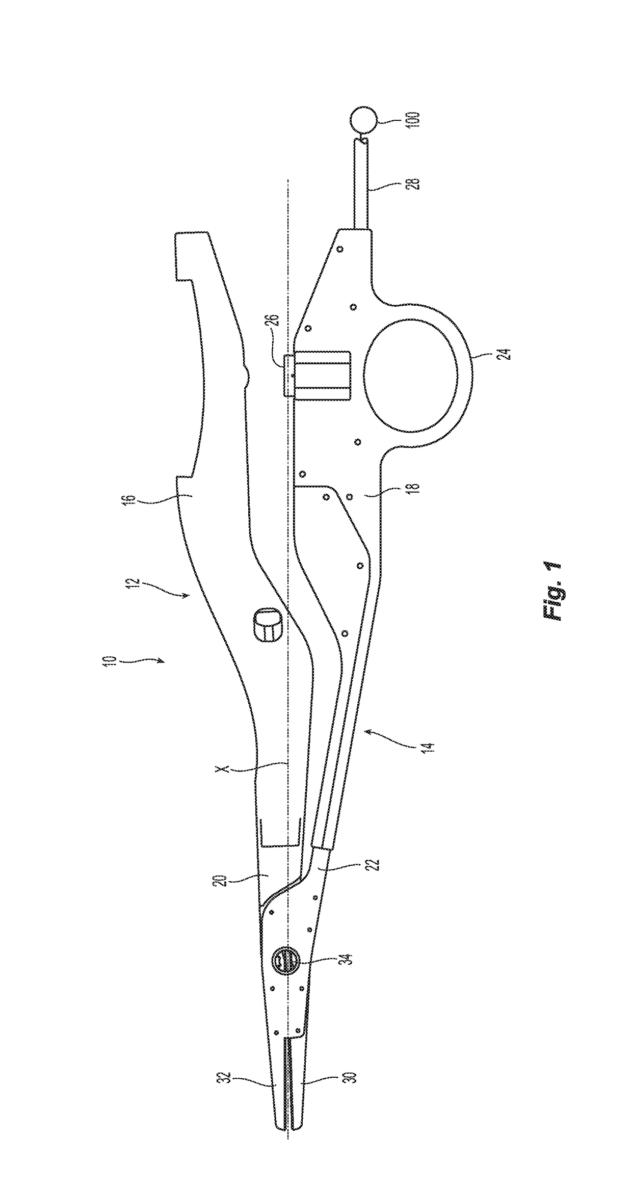
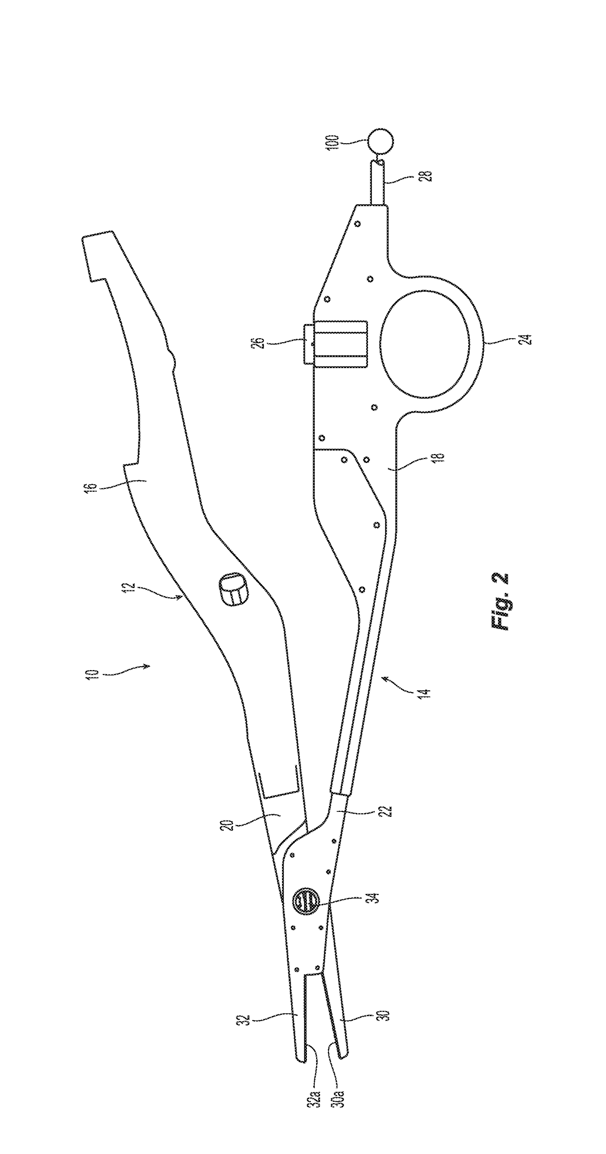
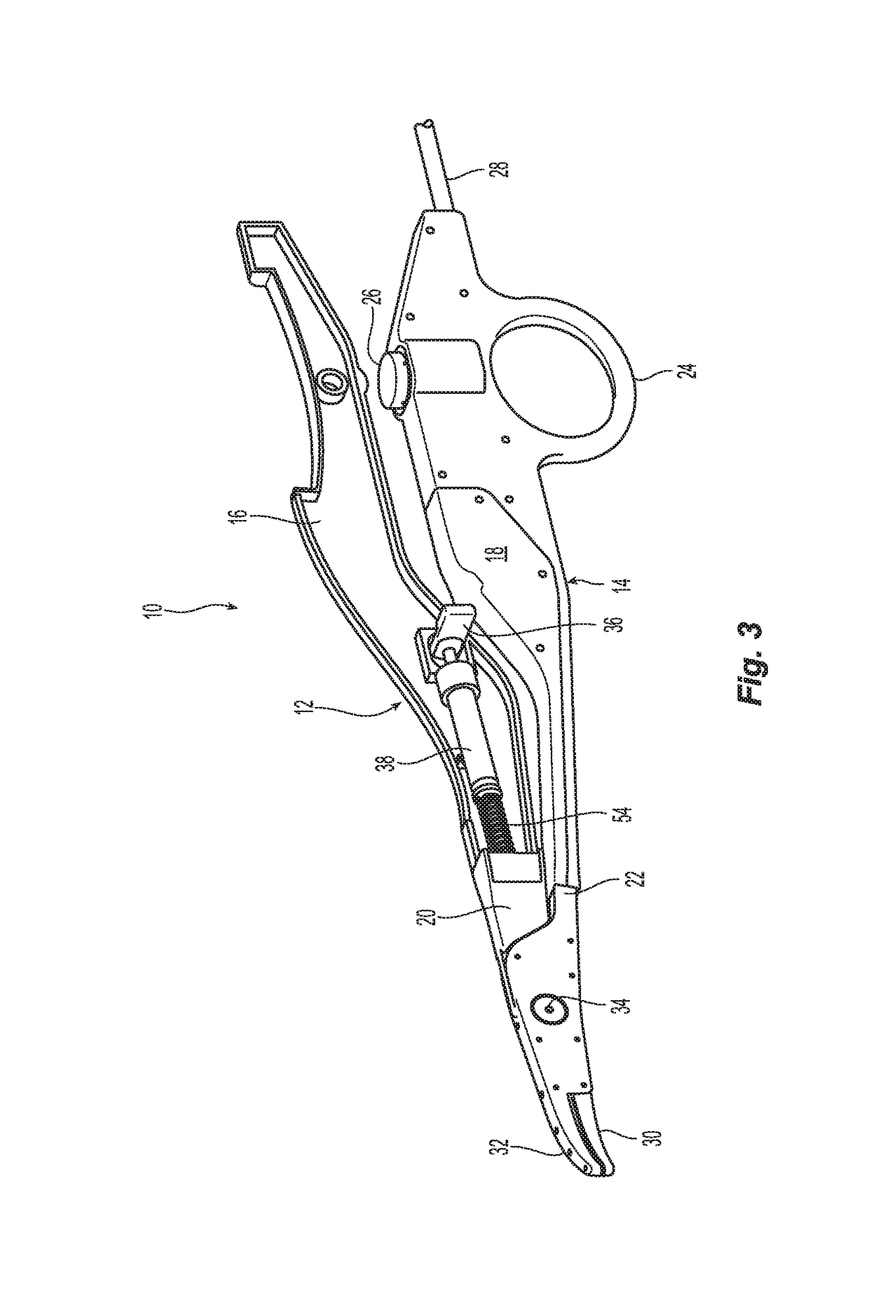
[0024]Referring initially to FIGS. 1-2, the electrosurgical forceps 10 of the present disclosure is illustrated. The electrosurgical forceps 10 includes a first member 12 and a second member 14 operatively coupled to each other and extending generally along a longitudinal axis “k”. The first and second members 12, 14 include respective first and second housings 16, 18 having first and second shafts 20, 22 depending from the first and second housings 16, 18. The first and second housings 16, 18 are configured for manual engagement by the clinician, i.e., form the handle of the el...


PUM


Abstract

An electrosurgical forceps includes a hydraulic knife mechanism adapted to increase linear movement of the cutting blade while minimizing movement of the manually manipulative actuator or trigger.

Description

BACKGROUND1. Technical Field[0001]The present disclosure relates to an electrosurgical apparatus and, more particularly, relates to energy-based surgical forceps for treating, sealing and / or cutting tissue.2. Background of Related Art[0002]An electrosurgical apparatus applies high frequency electric current to cut, coagulate and / or cauterize tissue. A conventional electrosurgical apparatus is an electrosurgical forceps which is a plier-like instrument relying on mechanical action between its jaws to grasp, clamp, and constrict tissue. The jaws are adapted for relative movement, e.g., between open and approximated conditions. A knife is typically incorporated within the forceps to sever the treated tissue. However, known knife deployment mechanisms are complex in design often requiring multiple linkage mechanisms to obtain the desired travel of the knife relative to the jaws. This increases the overall size of the handle and the range of movement required by the clinician to manipula...

Claims


Application Information

Patent Timeline
IPC IPC(8): A61B18/14
CPCA61B18/1442A61B2017/00539A61B2018/00297A61B2018/00922A61B2018/1455A61B2018/00601A61B2018/0063A61B2018/00773A61B2018/00875A61B34/30
Inventor MUJAWAR, ARIFMOHAMAD H.YENDURU, VAKULA
Owner TYCO HEALTHCARE GRP LP
Learn More