
Two coupled vehicles such as railbound vehicles or articulated busses, with a connection with at least one bellows as well as one coupling device, comprising two coupling elements

Active Publication Date: 2008-12-18
HUBNER GMBH
View PDF7 Cites 2 Cited by
  • Summary
  • Abstract
  • Description
  • Claims
  • Application Information

AI Technical Summary

Benefits of technology

[0016]According to a particular feature of the invention, there is provided that the force transmitting member is disposed for free movement in the groove of the coupling element or of the coupling frame. Free movement means in this context that the force transmitting member only lies in the groove but is free to move at its ends, meaning that it is not fixed in any way in the groove at one end. This means that complex Bowden cable constructs as they are partially needed in prior art are not needed here. This is substantially due to the fact that the force transmitting member is configured to be rigid and still highly flexible, meaning that it is made for example from spring steel or from glass fiber reinforced plastic and that it is thus capable of transmitting both tensile and pressure forces. In this context, there is particularly provided that two force transmitting members are disposed each for free movement in the circumferential groove of the coupling frame in the direction of their longitudinal axis. This means that the force transmitting member needs not necessarily surround the entire perimeter e.g., in an approximately rectangular coupling frame, but that for example two such force transmitting members, which are diagonally opposite, are placed in the groove of the coupling frame and ensure the movement of the locking members. This offers the advantage that each force transmitting member needs only extend about one corner of e.g., the coupling frame and not about all four corners as this would be the case if the force transmitting member were to extend over the entire perimeter of the coupling frame. This permits to strongly minimize the friction in the region of the groove, in particular in the corner region, thus substantially facilitating actuation for unlocking or locking.

Problems solved by technology

This known device for coupling two coupling frames is very expensive due to the great number of different component parts.

Method used


Image

  • Two coupled vehicles such as railbound vehicles or articulated busses, with a connection with at least one bellows as well as one coupling device, comprising two coupling elements
  • Two coupled vehicles such as railbound vehicles or articulated busses, with a connection with at least one bellows as well as one coupling device, comprising two coupling elements
  • Two coupled vehicles such as railbound vehicles or articulated busses, with a connection with at least one bellows as well as one coupling device, comprising two coupling elements

Examples


Embodiment Construction

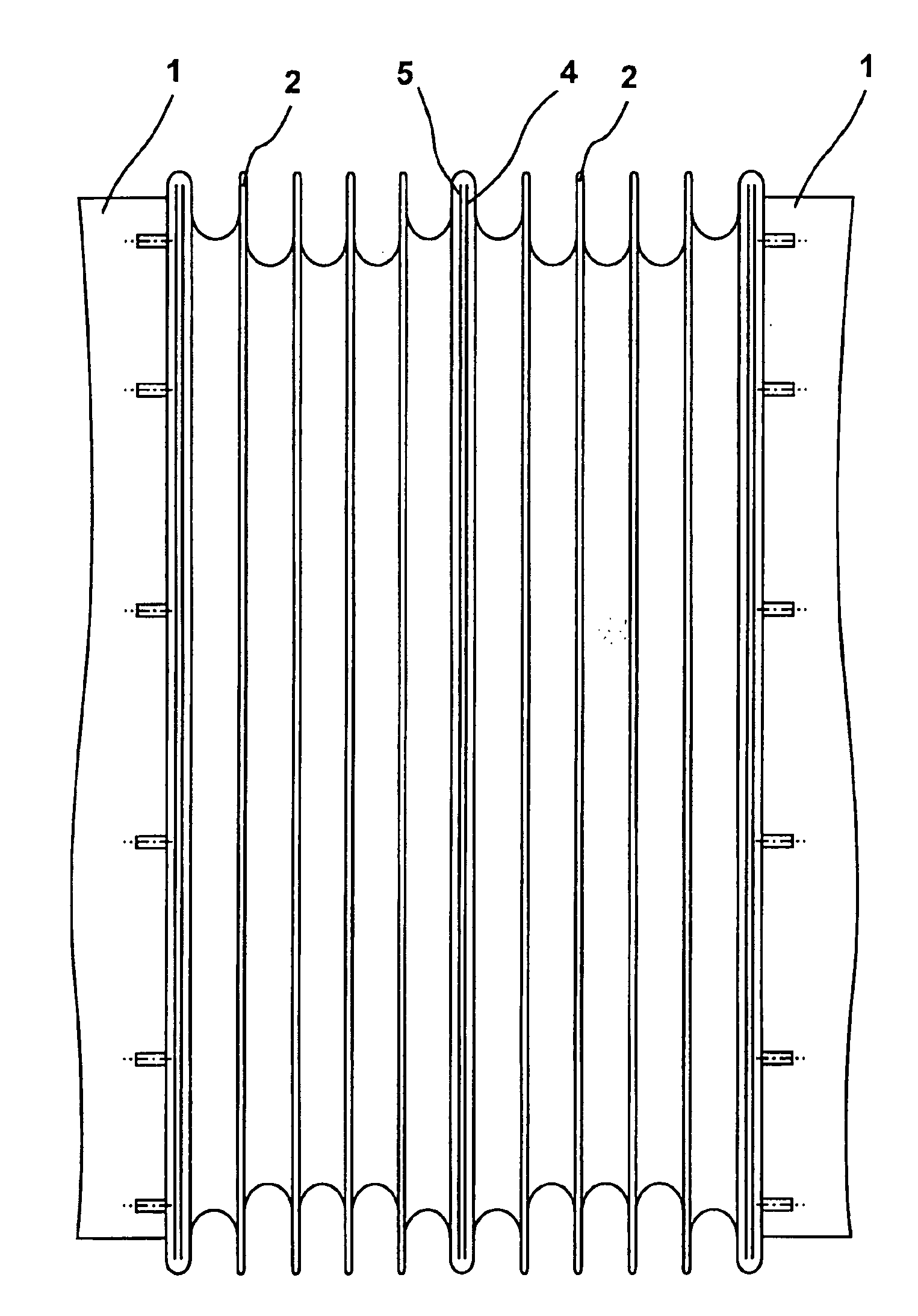
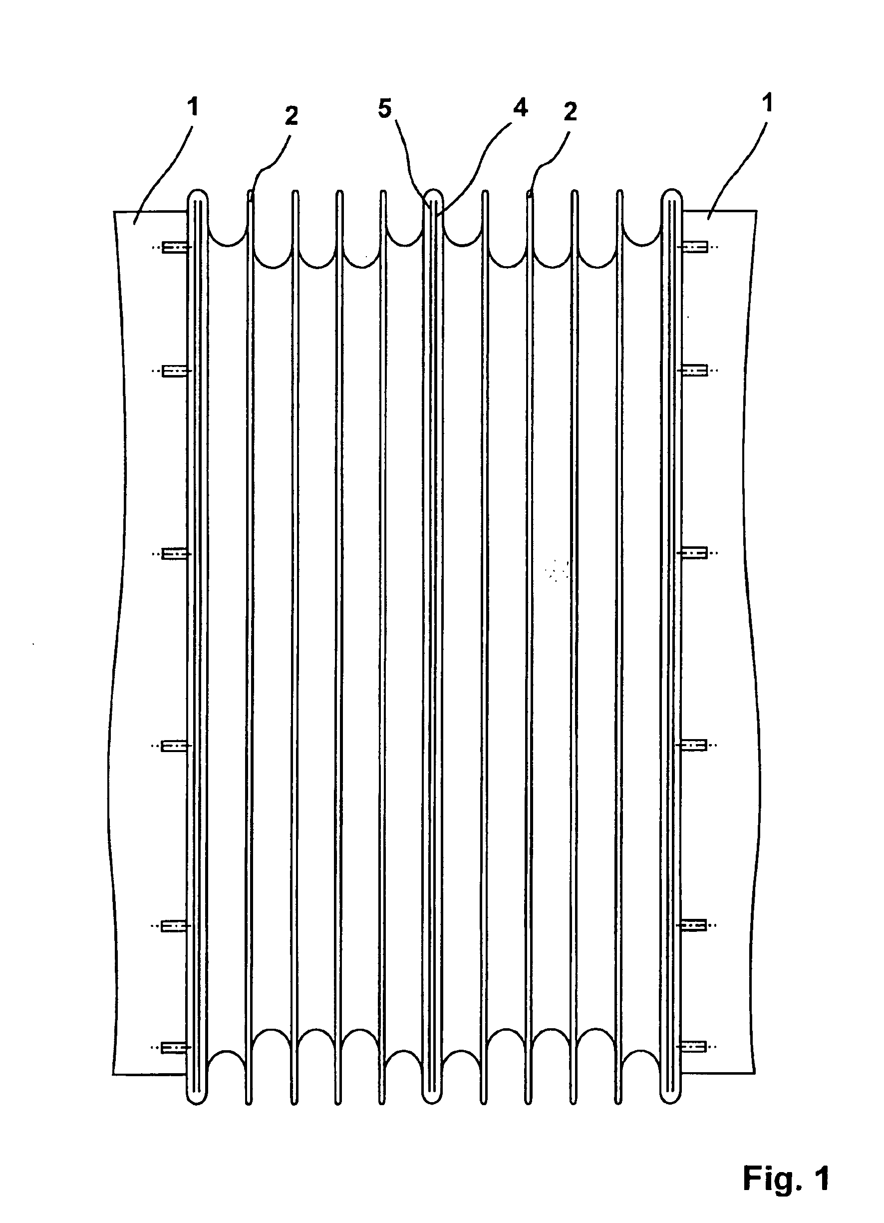
[0034]Referring to FIG. 1, the two vehicle parts are indicated at 1, the bellows consisting of two halves 2 being interposed between the two vehicle parts. The two bellows halves 2 each comprise at their front side ends that are turned toward each other one coupling frame 4, 5 through which the two bellows halves 2 may be coupled together.

[0035]It is desired to explicitly note here that the invention also comprises an embodiment in which the bellows is directly coupled to the car body, meaning that a coupling frame is solidly mounted in particular to the car body, said coupling frame being adapted for coupling to the coupling frame of the bellows or to the end wall of the car body forming the coupling frame.

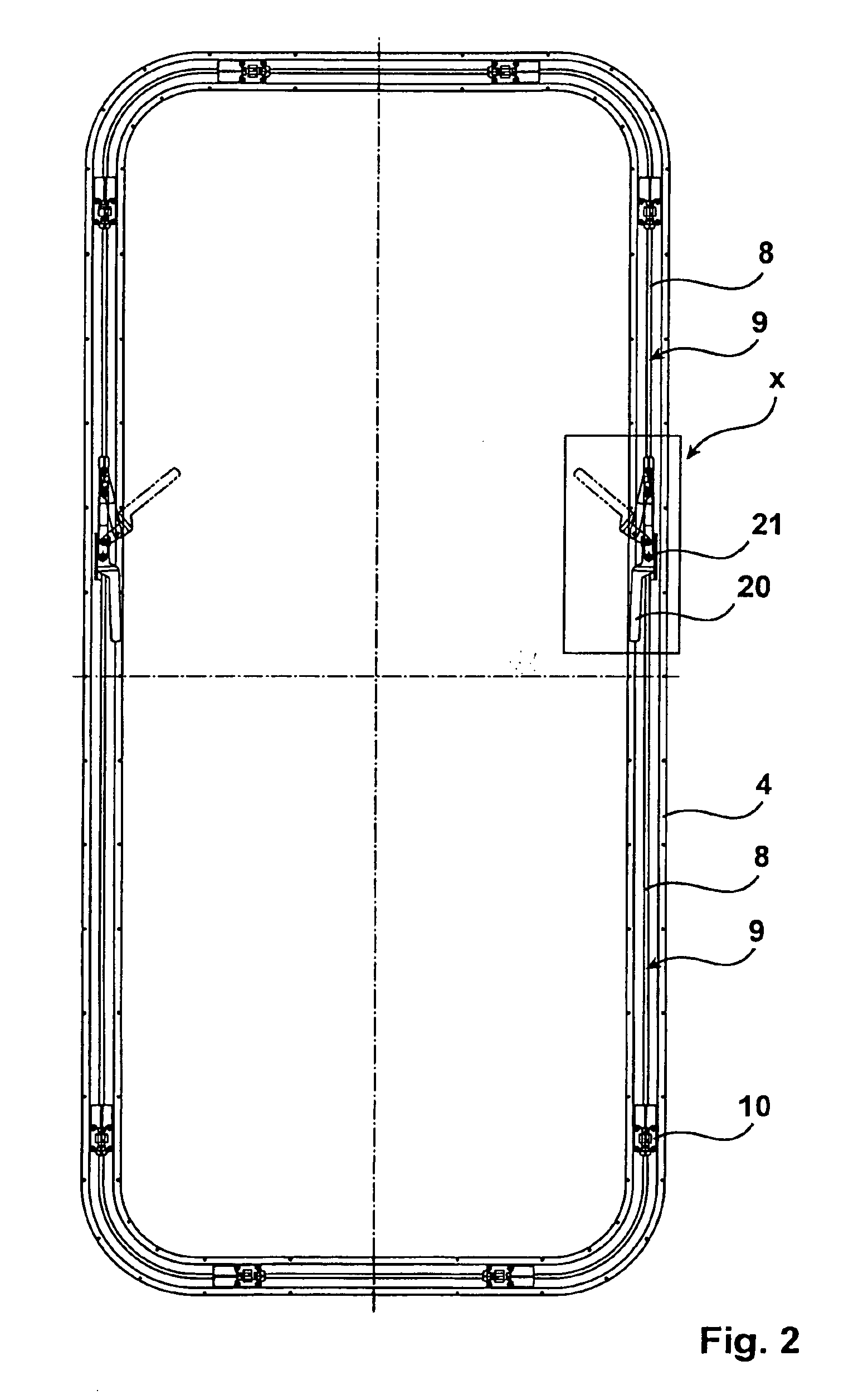
[0036]The configuration of the coupling frame is visible from FIG. 2. In the present case, the coupling frame illustrated in FIG. 2 only comprises female coupling members 10 and no male coupling members 15. It is possible to combine both male and female coupling members and to di...


PUM


Abstract

The invention is directed to two coupled vehicles (1) such as railbound vehicles or articulated busses, with a connection with at least one bellows (2) as well as with a coupling device comprising two coupling frames (4, 5), said coupling frames (4, 5) comprising interengaging male and female coupling members (10, 15), a locking member (30) being provided for respectively locking the male coupling members (15) in the female coupling members (10), said locking member (30) being slidably guided by the respective locking member (4, 5), said locking member (30) communicating with a force transmitting member (9) that is slidably guided in the respective one of the coupling frames (4, 5), the force transmitting member (9) transmitting both tensile and shear forces.

Description

CROSS-REFERENCE TO RELATED APPLICATIONS[0001]This application claims Priority from German Application No. EP 07011654.6 filed on 14 Jun. 2007[0002]1. Field of the Invention[0003]The present invention relates to two coupled vehicles such as railbound vehicles or articulated busses, with a connection with at least one bellows as well as with a coupling device comprising two coupling elements.[0004]On coupled vehicles such as railbound vehicles or articulated busses, what is referred to as a connection is provided between the discrete vehicles parts. Purely conceptually, such a connection comprises a gangway for allowing passengers to transit between one vehicle part and the other as well as a bellows with an approximately rectangular cross section that encloses at least the gangway, in most cases however also the hinge connection through which the two vehicle parts are connected together.[0005]2. Description of the Prior Art[0006]To fasten the bellows to the front side of the vehicle,...

Claims


Application Information

Patent Timeline
IPC IPC(8): B60D5/00
CPCB60D5/003B61D17/22B62D47/025B61D17/20
Inventor GOEBELS, ANDRERUDOLPH, HANS-JAKOB
Owner HUBNER GMBH
Learn More