Valve

Active Publication Date: 2020-01-28
HYDAC FLUITECHNIK GMBH
View PDF25 Cites 0 Cited by
  • Summary
  • Abstract
  • Description
  • Claims
  • Application Information

AI Technical Summary

Benefits of technology

[0008]This problem is basically solved by a valve having the valve piston arrive at a floating position inside the valve housing by a hydraulic stroke limit or stop for maintenance of the dither signal. The valve piston is thereby prevented from striking the additionally provided mechanical stroke limit, as has been described in the prior art, with the described negative consequences for the dither signal effect. Because the valve according to the invention now has a hydraulic stroke limit, from a hydraulic perspective an additional control edge has been created, which additional control edge permits a fluidic force build-up on the valve piston. The fluidic force is greater than the effective magnetic force of the actuating magnet acting upon the valve piston, so that the valve piston can be stopped shortly before it reaches the mechanical stroke limit. In this respect, the valve piston then remains floating or in a kind of floating state, and the dither signal effect procured via the actuating magnet is fully maintained. Then, the friction is still minimized, and functional impairments are ruled out in this r

Problems solved by technology

However, in the case of large construction machines, for example earth-moving machines such as diggers, the directional valves of the working hydraulics reach piston diameters at which pilot control with directly controlled proportional pressure control valves is no longer practical.
The large slide valves produce during rapid switching a flow of pilot oil that can no longer be tolerated by the small pilot valves.
The large piston can, however, allow the passage of a significantly larger volume flow compared with the directly controlled valve, and thus, drastically reduce, in a desirable manner, the switching times of the large slide valves.
The leakage of these va

Method used


Image

  • Valve
  • Valve

Examples


Embodiment Construction

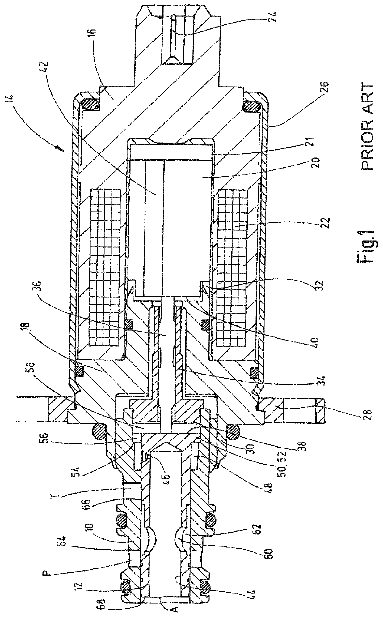
[0015]FIG. 1 shows a longitudinal section depiction of a valve in the form of a proportional pressure control valve known from the prior art. The valve has a valve housing 10 with a valve piston 12, which is guided in a longitudinally displaceable manner in the housing 10. This valve piston 12 serves for alternately releasing and connecting a utility connection A to a pressure supply connection P or a tank connection T. The utility connection A is also referred to as a working connection in technical parlance. For the supply connection P, the term pump connection has also become generally accepted. The tank connection T need not necessarily lead to a supply tank; instead, this description is only intended to indicate that a relatively low pressure is applied at the connection T, for example a tank and / or ambient pressure. The utility connection or working connection A is mounted on the front face of the valve housing 10. Both the pressure supply connection or pump connection P and t...


PUM


Abstract

A valve, in particular a proportional pressure regulating valve, has a valve piston (12) longitudinally movable in a valve housing (10) for alternately releasing and connecting a user connection (A) to a pressure supply port (P) or a tank connection (T). The valve piston can be actuated by an actuating magnet (14) that produces a dither signal during operation. The valve piston (12) reaches a floating position within the valve housing (10) by a hydraulic lift limitation for the receipt of the dither signal.

Description

FIELD OF THE INVENTION[0001]The invention relates to a valve, in particular a proportional pressure control valve, comprising a valve piston longitudinally displaceable in a valve housing for alternately releasing and connecting a utility connection or consumer connection A to a pressure supply connection P or a tank connection T. The valve piston being able to be actuated by an actuating magnet, which produces a dither signal during operation.BACKGROUND OF THE INVENTION[0002]Valves, such as proportional pressure control valves, are very commonly used in mobile work machines for electrohydraulic pilot control of directional valves. One example of such a valve is disclosed in WO 2010 / 085991 A2.[0003]For “smaller devices”, directly controlled proportional pressure control valves are usually sufficient. However, in the case of large construction machines, for example earth-moving machines such as diggers, the directional valves of the working hydraulics reach piston diameters at which ...

Claims


Application Information

Patent Timeline
IPC IPC(8): F15B13/04F16K11/07F16K31/06F15B13/044F16K29/00
CPCF16K31/0689F16K31/0613F16K11/0716F15B13/0407F15B13/0402Y10T137/86694F16K29/00Y10T137/86702F15B13/044
Inventor BRUCK, PETER
Owner HYDAC FLUITECHNIK GMBH
Why Eureka
Try Eureka