
Door hinge height adjusting device for rotating door

Active Publication Date: 2017-10-26
FILOBE
View PDF0 Cites 0 Cited by
  • Summary
  • Abstract
  • Description
  • Claims
  • Application Information

AI Technical Summary

Benefits of technology

The present invention provides a door hinge height adjusting device that can accurately control the vertical displacement or distance between two support brackets, even when the weight of a door results in a rotary movement. This device helps minimize friction and noise generation, especially in the case of a gear hinge part.

Problems solved by technology

However, since strength against a rotational moment on a vertical surface which is generated between an upper end and a lower end of the door is weak, a size and strength of a hinge joint part and a size and strength of a fixing means (an anchor) thereof should also be increased when the door becomes bigger, and thus it is difficult for the door to become bigger.
In addition, since a response that satisfies a customer requirement for minimizing and slimming a cross-sectional dimension of the door (or a cross-sectional dimension of the door frame for supporting a window constituting the door) while enlarging a size of the door and a an increase of the size of the fixing means (the anchor) conflict with each other, there is a limit in solving the problem.
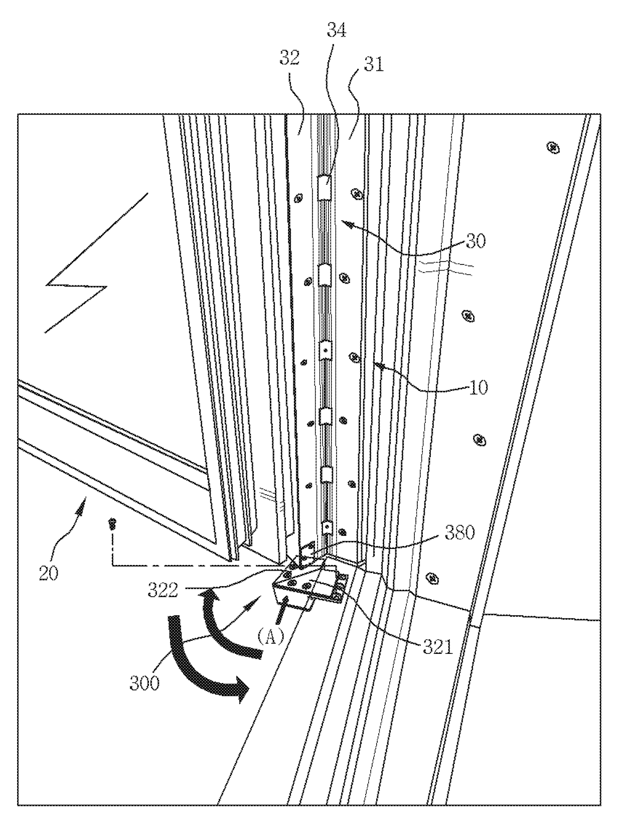
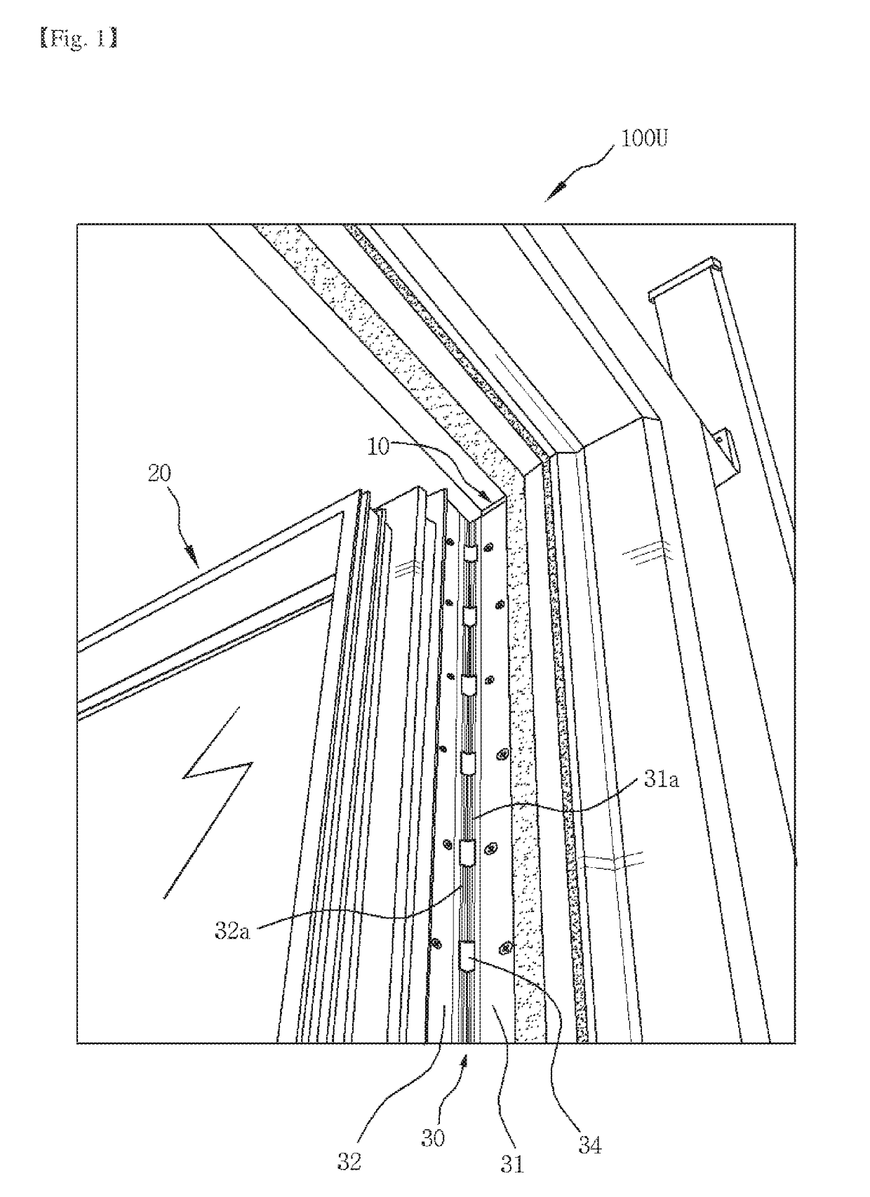
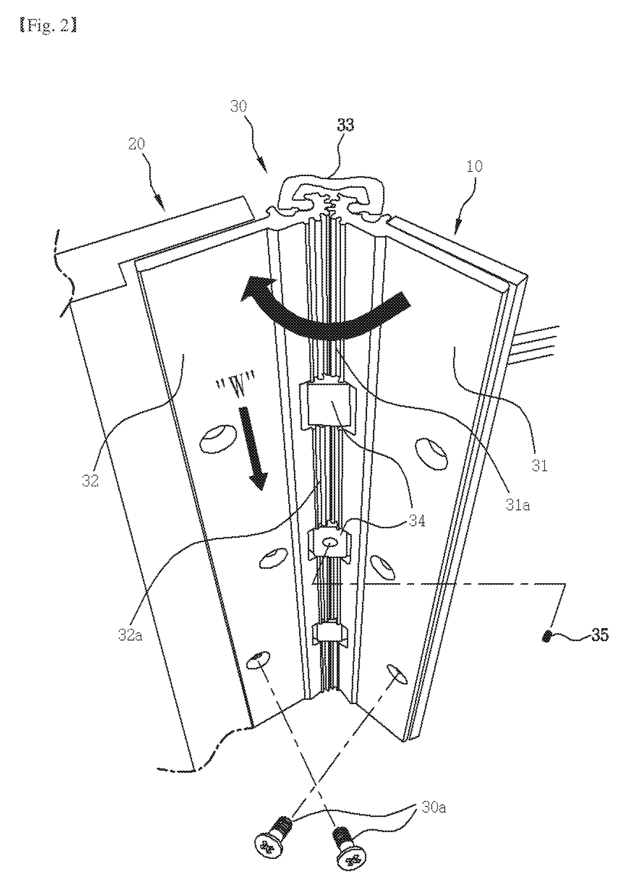
However, in an actual situation in which the large-sized door 20 is installed at the support frame 10 of the door frame through the above-mentioned gear hinge part 30, as illustrated in FIG. 12, a downward displacement induced on the second support bracket 32 fixedly connected to the side of the door 20 by a weight W of the door 20 increases a friction force at a cross section contacting the vertical hooking tool 34, and thus friction noise is excessively generated when the door is rotated to be opened and closed.
There is a problem in that it is difficult to avoid friction noise generated at the large-sized door with only the above-mentioned material solution.
However, it is almost impossible to precisely adjust a height in a range of 0.1 mm to 0.5 mm using such lifting devices, and excessive expense is entailed in making it possible.
As long as a structure in which a vertical displacement or distance may occur between components forming a door hinge part of a rotary door is provided, substantially the same technical problems as those in the gear hinge part will be generated even when a detailed configuration of the hinge part is changed.

Method used


Image

  • Door hinge height adjusting device for rotating door
  • Door hinge height adjusting device for rotating door
  • Door hinge height adjusting device for rotating door

Examples


Embodiment Construction

[0040]Hereinafter, exemplary embodiments of the present invention will be described in detail below with reference to the accompanying drawings to be easily implemented by those skilled in the art. However, the present invention may be embodied in different forms and is not to be construed as limited to the embodiments set forth herein.

[0041]FIG. 13 is a view illustrating a state in which a door hinge height adjusting device for rotating a door according to the present invention is installed at a rotary door, FIG. 14 is a view illustrating one preferred embodiment of the door hinge height adjusting device for rotating a door according to the present invention, FIG. 15 is a partially exploded perspective view of one embodiment of the door hinge height adjusting device for rotating a door of FIG. 14, and FIG. 16 is a view illustrating a state in which the number of height adjusting thin plates in FIG. 15 is increased by one.

[0042]First, one preferred embodiment of the door hinge heigh...


PUM


Abstract

The present invention relates to a door hinge height adjusting device that can adjust the relative vertical position of a second support bracket with respect to a first support bracket in a door hinge that rotatably connects one side surface of a door forming a rotating door to a support frame in a door frame, the door hinge comprising: the first support bracket which is fixedly connected to the support frame side of a door frame; the second support bracket which is fixedly connected to the door side; and a hinge portion which is provided between the first support bracket and the second support bracket, for relative rotation.

Description

TECHNICAL FIELD[0001]The present invention relates to a device which is capable of adjusting a relative vertical position between a first support bracket fixedly connected to a side of a support frame of a door frame and a second support bracket fixedly connected to a side of a door in a door hinge for connecting between a door forming a rotary door and the support frame of the door frame, and more particularly, to a door hinge height adjusting device for rotating a door which allows vertical displacement, which may be generated at a hinge part due to various factors such as a construction error generated when the door is constructed and downward deflection of a second support bracket due to a weight of the door, to be corrected, and is thus capable of ensuring and maintaining an exact opening and closing function of a door and also minimizing generation of friction noise or damage to a component due to friction generated at a door hinge in a door hinge in which a hinge part is prov...

Claims


Application Information

Patent Timeline
IPC IPC(8): E05D7/04E05D11/06E05D11/00E05D1/00E05D7/00
CPCE05D7/04E05D11/00E05D11/06E05D2007/0469E05D7/009E05Y2900/132E05D1/00E05D7/0027E05D3/122
Inventor LEE, KWANG-SEOK
Owner FILOBE
Learn More