Cable guide for a bicycle suspension fork

Active Publication Date: 2005-05-26
SRAM CORPORATION
View PDF6 Cites 1 Cited by
  • Summary
  • Abstract
  • Description
  • Claims
  • Application Information

AI Technical Summary

Benefits of technology

[0006] The present invention provides a cable guide for a control cable extending between an actuator and a suspension system including a crown connecting two parallel tubular bodies to a steerer tube. The cable guide includes a housing formed on the crown and having

Problems solved by technology

Further, the 180-degree change in direction of the control cable between the first and second spools, adds friction, thereby reducing the life of the control cable.
The additional spool 110 also makes the design more costly and compli

Method used


Image

  • Cable guide for a bicycle suspension fork
  • Cable guide for a bicycle suspension fork
  • Cable guide for a bicycle suspension fork

Examples


Example

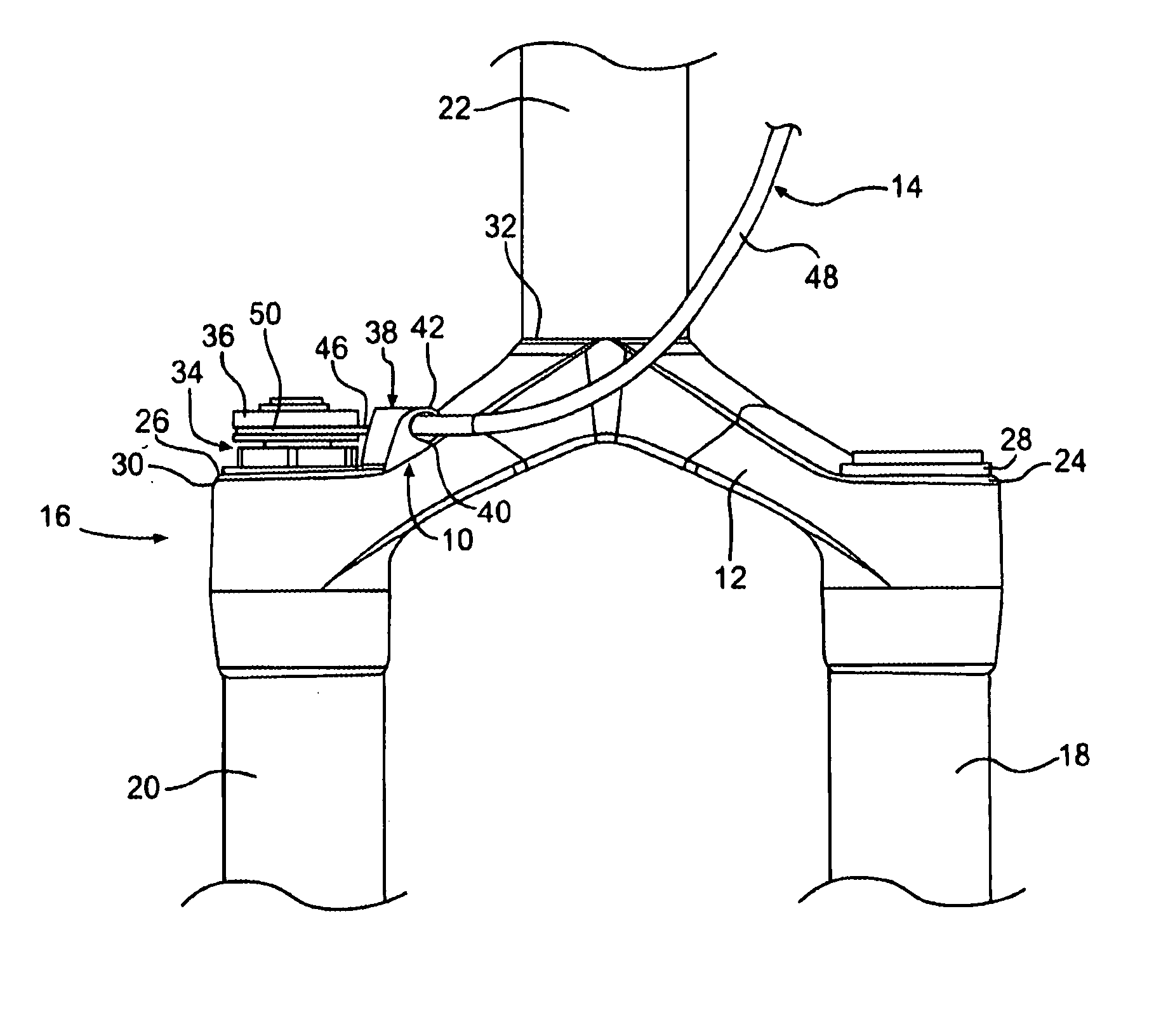
[0015]FIGS. 3-5 illustrate a cable guide 10 in accordance with one embodiment of the present invention. As shown in FIG. 3, the cable guide 10 is located on a crown 12 for a bicycle front suspension fork. The cable guide 10 directs a control cable 14 extending between an actuator, such as a lever located on a handlebar, and a bicycle suspension system 16.

[0016] The crown 12 is a portion of the suspension fork 16 that connects two fork legs 18, 20 to a steerer tube 22. The crown 12 is forged for strength. The leg 18 may contain a spring assembly, and the other leg 20 may contain a damping mechanism (not shown). The crown 12 includes two bores 24, 26 extending therethrough for receiving ends 28, 30 of the legs 18, 20, respectively. The other ends of the legs (not shown) are connected to a wheel axle. The crown 12 further includes a third bore 32 located between the two openings 24, 26 for receiving the steerer tube 22. The legs 18, 20 and steerer tube 22 may be press fit into the ope...


PUM


Abstract

A cable guide routing a control cable that extends between an actuator and a suspension system having a crown connecting two parallel tubular bodies to a steerer tube. The cable guide includes a housing formed on the crown and having a bore extending therethrough for receiving the control cable. The suspension system includes a spool located on an end of one of the tubular bodies for winding and unwinding the control cable. The housing is configured on the suspension system such that a portion of the control cable extending between the housing and the spool lies substantially in a plane of the spool. So configured, friction is minimized.

Description

BACKGROUND OF INVENTION [0001] The present invention relates to cable guides for bicycles, and more particularly to a cable guide for a control cable extending between an actuator and a suspension system. [0002] Bicycle suspension systems are designed to absorb the impacts and vibrations typically experienced by riders when the bicycle traverses irregularities on the riding surface. Some suspension systems are provided with a lockout mechanism that turns the suspension on or off. When the suspension is on, it is compliant and displaces in response to bumps in the road. When the suspension is off or “locked out,” it becomes substantially rigid and does not displace in response to road irregularities. Additionally, suspension systems have been provided with control devices that adjust the characteristics of the suspension such as travel and spring rate. Typically, a rider operates these control devices by turning a knob located at the top or the bottom of the fork. So located, the rid...

Claims


Application Information

Patent Timeline
IPC IPC(8): B62K19/30B62K21/04B62K25/08
CPCB62K19/30B62K21/04Y10T74/20438Y10T74/20402B62K25/08
Inventor WESLING, KEVIN
Owner SRAM CORPORATION
Why Eureka
Try Eureka