Accumulator

Active Publication Date: 2017-01-19
FUJIKOKI CORP
View PDF15 Cites 4 Cited by
  • Summary
  • Abstract
  • Description
  • Claims
  • Application Information

AI Technical Summary

Benefits of technology

The present invention aims to provide an accumulator that can effectively suppress bumping and impact noise during the starting of a compressor without increasing the cost and size of the accumulator. The accumulator includes a cloth-like member or the like that serves as a boiling stone, which leads to a gradual vaporization of the liquid-phase refrigerant and prevents the sudden bumping and impact noise. Additionally, a desiccant storage part is included in the accumulator, which improves the cost-effectiveness of the accumulator.

Problems solved by technology

According to the aforementioned conventionally proposed techniques, however, means for agitating, including an agitating blade, a driving source to rotate the blade, a bypass channel having an open / close valve and the like is required separately, which may lead to the problems that the structure of the accumulator (and a heat pump system including it) becomes complicated, or the cost and the size thereof increase.

Method used


Image

  • Accumulator
  • Accumulator
  • Accumulator

Examples


embodiment 1

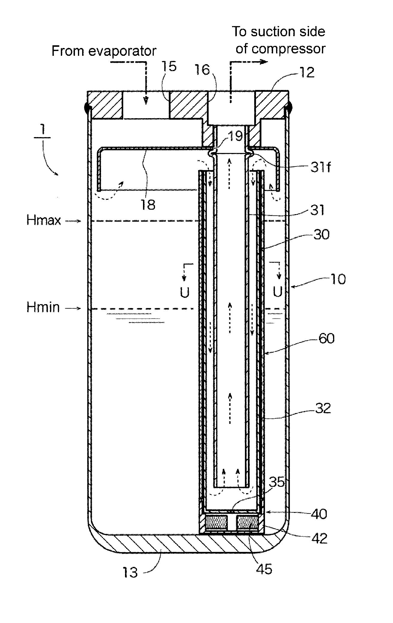
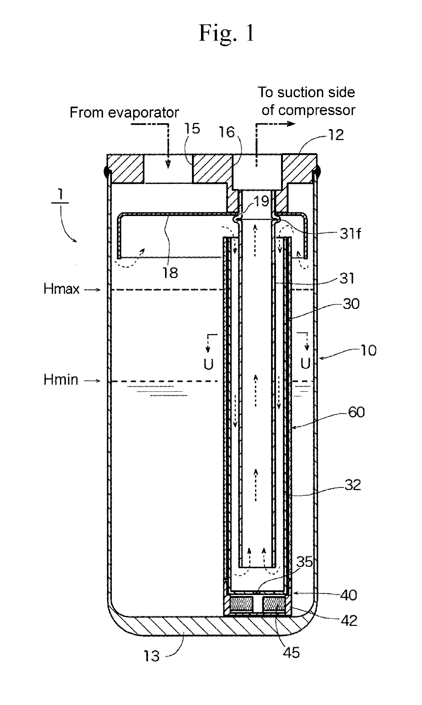
[0038]FIG. 1 is a partially cutaway front view showing Embodiment 1 of an accumulator according to the present invention, and FIG. 2 is an enlarged cross-sectional view taken along the arrow U-U of FIG. 1.

[0039]An accumulator 1 of Embodiment 1 in the drawing can be used as the accumulator 250 in the heat pump system 200 making up a car air-conditioner for electric vehicles, for example, as shown in FIGS. 7A and 7B as stated above, and includes a bottomed cylindrical tank 10 made of metal, such as stainless steel or aluminum alloy, where the upper opening of this tank 10 is hermetically sealed with a lid member 12 made of the same metal. Note here that the accumulator 1 of the present embodiment is installed vertically as illustrated, for example, i.e., the lid member 12 is located above (top) and a bottom 13 of the tank 10 is located below (bottom).

[0040]The lid member 12 has an inflow port 15 and a stepped outflow port 16 disposed side by side, a gas-liquid separating member 18 is ...

embodiment 2

[0054]FIG. 5 is a partially cutaway front view showing Embodiment 2 of an accumulator according to the present invention, and FIG. 6 is an enlarged cross-sectional view taken along the arrow X-X of FIG. 5.

[0055]An accumulator 2 of Embodiment 2 shown in the drawing is different from the accumulator 1 of Embodiment 1 in that a cloth-like member 70, such as felt, is provided with an externally-inserted part 72 that is externally inserted for fixing to the outer periphery of the outer pipe 32, and with a cylindrical desiccant storage part 75 whose top and bottom are blocked to store desiccant M to absorb and remove water in the refrigerant, and the configuration in the other respects is the same. In FIGS. 5 and 6 showing the accumulator 2 of Embodiment 2, the same reference numerals are assigned to the parts corresponding to those of the accumulator 1 of Embodiment 1.

[0056]The desiccant storage part 75 is disposed vertically (along the axial line of the outer pipe 32) and externally to ...


PUM


Abstract

Provided is an accumulator capable of effectively suppressing a bumping phenomenon and the following impact noise during the starting of a compressor without making the structure of the accumulator complicated or increasing the cost and the size thereof, and so having cost-effectiveness. An accumulator includes: a tank 10 having an inflow port 15 and an outflow port 16; and a double-pipe structured outflow pipe 30 including an inner pipe 31 joined to the outflow port 16 and hanging inside of the tank 10, and an outer pipe 32 disposed outside of the inner pipe 31. A cloth-like member such as felt or a foam material 60 is wound around or externally inserted to the outer pipe 32.

Description

RELATED APPLICATIONS[0001]The present application claims priority from Japanese patent application JP 2015-143242 filed on Jul. 17, 2015, the content of which is hereby incorporated by reference into this application.BACKGROUND OF THE INVENTION[0002]1. Field of the Invention[0003]The present invention relates to an accumulator (gas-liquid separator) used for a heat pump-type refrigerating cycle (hereinafter called a heat pump system), such as a car air-conditioner, a room air-conditioner, or a freezing machine.[0004]2. Description of the Related Art[0005]As illustrated in FIGS. 7A and 7B, a heat pump system 200 making up a car air-conditioner or the like typically includes a compressor 210, an outdoor heat exchanger 220, an indoor heat exchanger 230, an expansion valve 260, a four-way switching valve 240 and the like, as well as an accumulator 250.[0006]In such a heat pump system 200, switching (channel switching) between cooling operation and heating operation is performed by the f...

Claims


Application Information

Patent Timeline
IPC IPC(8): F25B43/00
CPCF25B2400/03F25B43/006F25B43/00F25B43/003F25B2500/12
Inventor HOSOKAWA, KOUJI
Owner FUJIKOKI CORP
Why Eureka
Try Eureka