Hydraulic pressure valve apparatus

a valve apparatus and hydraulic pressure technology, applied in the field of variable valve apparatus, can solve the problems of limited valve lift, small moment of inertia and accumulation clearance, and limited development of dynamic characteristics of valves, and achieve the effect of suppressing impact noise and minimizing hydraulic pressure peak

Active Publication Date: 2012-11-08
HYUNDAI MOTOR CO LTD
View PDF1 Cites 0 Cited by
  • Summary
  • Abstract
  • Description
  • Claims
  • Application Information

AI Technical Summary

Benefits of technology

[0014]Various aspects of the present invention provide for a hydraulic pressure valve apparatus which may minimize hydraulic pressure peak so as to suppress impact noise.
[0034]A hydraulic pressure valve apparatus according to various aspects of the present invention may minimize hydraulic pressure peak so as to suppress impact noise.

Problems solved by technology

However, since a CVVL (continuous variable valve lift apparatus) which is controlled mechanically, uses a link, eccentric cam a control shaft and so on, so that moment of inertia and accumulated clearance is relatively large, and development of dynamic characteristic of a valve is limited.
Also, each valve is controlled by the same camshaft simultaneously, realizing valve lift is limited.

Method used


Image

  • Hydraulic pressure valve apparatus
  • Hydraulic pressure valve apparatus
  • Hydraulic pressure valve apparatus

Examples


Embodiment Construction

[0040]Reference will now be made in detail to various embodiments of the present invention(s), examples of which are illustrated in the accompanying drawings and described below. While the invention(s) will be described in conjunction with exemplary embodiments, it will be understood that present description is not intended to limit the invention(s) to those exemplary embodiments. On the contrary, the invention(s) is / are intended to cover not only the exemplary embodiments, but also various alternatives, modifications, equivalents and other embodiments, which may be included within the spirit and scope of the invention as defined by the appended claims.

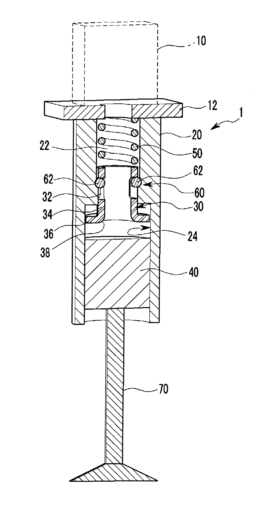
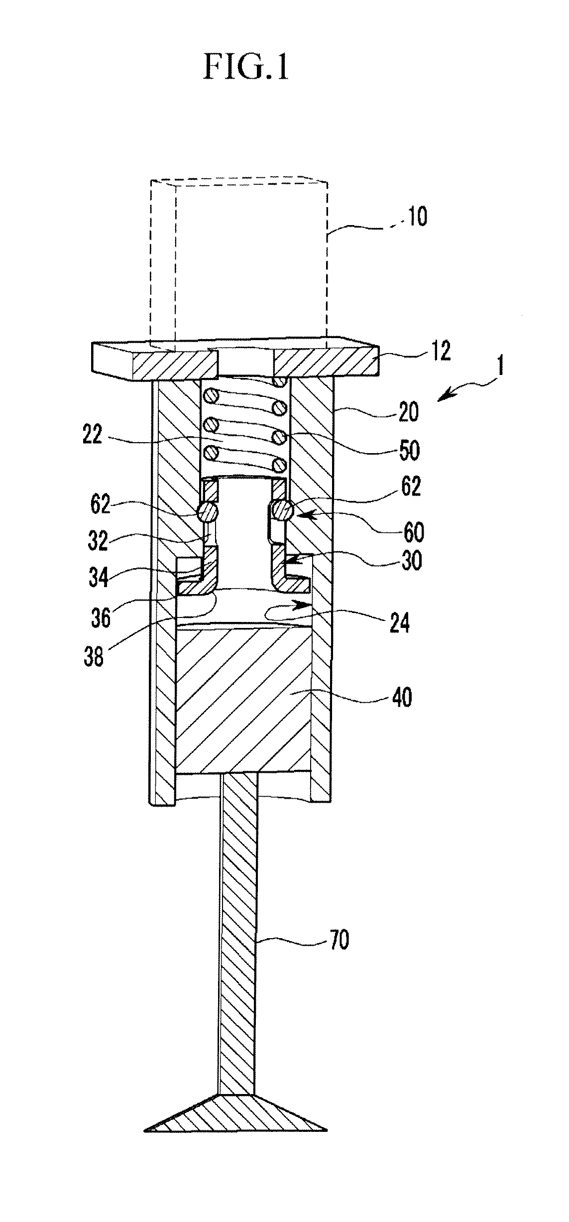
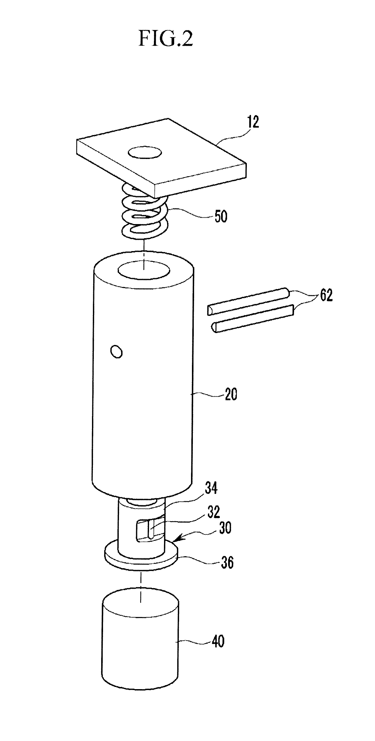
[0041]FIG. 1 is a cross-sectional view of a hydraulic pressure valve apparatus according to various embodiments of the present invention, and FIG. 2 is a developed view of a hydraulic pressure valve apparatus according to various embodiments of the present invention.

[0042]FIG. 3 to FIG. 6 are partial cross-sectional views of a hydraul...


PUM


Abstract

A hydraulic pressure valve apparatus includes a housing of which a first chamber and a second chamber are formed therein, wherein a diameter of the second chamber is bigger than that of the first chamber, a first piston disposed within the first chamber, an elastic portion disposed within the first chamber for elastically supporting the first piston and a second piston disposed within the second chamber and connected to a valve.

Description

CROSS-REFERENCE TO RELATED APPLICATION[0001]This application claims priority to and the benefit of Korean Patent Application No. 10-2011-0042617 filed May 4, 2011, the entire contents of which application is incorporated herein for all purposes by this reference.BACKGROUND OF INVENTION[0002]1. Field of Invention[0003]The present invention relates to a variable valve apparatus. More particularly, the present invention relates to a hydraulic pressure valve apparatus.[0004]2. Description of Related Art[0005]An internal combustion engine generates power by burning fuel in a combustion chamber in air media drawn into the chamber. Intake valves are operated by a camshaft in order to intake the air, and the air is drawn into the combustion chamber while the intake valves are open. In addition, exhaust valves are operated by the camshaft, and a combustion gas is exhausted from the combustion chamber while the exhaust valves are open.[0006]An optimal operation of the intake valves and the ex...

Claims


Application Information

Patent Timeline
Patent Type & Authority Applications(United States)
IPC IPC(8): F16K1/32F01L9/10
CPCF01L9/02F01L1/16F01L9/10F01L13/00
Inventor YANG, JEI CHOONYANG, CHANG HOCHOI, BYONG YOUNGKWAK, YOUNG HONGKONG, JIN KOOKWOO, SOO HYUNG
Owner HYUNDAI MOTOR CO LTD
Why Eureka
Try Eureka