Driving device and light-amount adjusting device provided with the same
a technology of adjusting device and driving device, which is applied in the direction of exposure control, dynamo-electric converter control, instruments, etc., can solve the problems of increasing the movement of the blade per step, reducing the power consumption of the diaphragm, and reducing the electrical angle of the mechanical angle. , to achieve the effect of preventing damage caused by repetitive abutments and suppressing impact nois
- Summary
- Abstract
- Description
- Claims
- Application Information
AI Technical Summary
Benefits of technology
Problems solved by technology
Method used
Image

Examples
first embodiment
[0020]FIG. 5 shows a configuration of a diaphragm device as a light-amount adjusting device according to a first embodiment of the present invention. In FIG. 5, reference numeral 101 denotes a base plate serving as a base of the diaphragm device. An opening 101a is formed at a central portion of the base plate 101. Reference numeral 102 denotes a windmill ring for allowing six diaphragm blades (described below) to perform opening / closing operation. The windmill ring 102 is attached to an object side surface of the base plate 101 around the opening 101a so as to be capable of rotating about an optical axis.
[0021] Reference numeral 103 denotes six diaphragm blades. A hole portion 103b and an elongated hole portion 103a are formed in each of the diaphragm blades 103. Fixing shaft portions 101b provided at six locations in a circumferential direction of the base plated 101 are each fitted into the hole portion 103b, and drive shaft portions 102a provided at six locations in a circumfer...
second embodiment
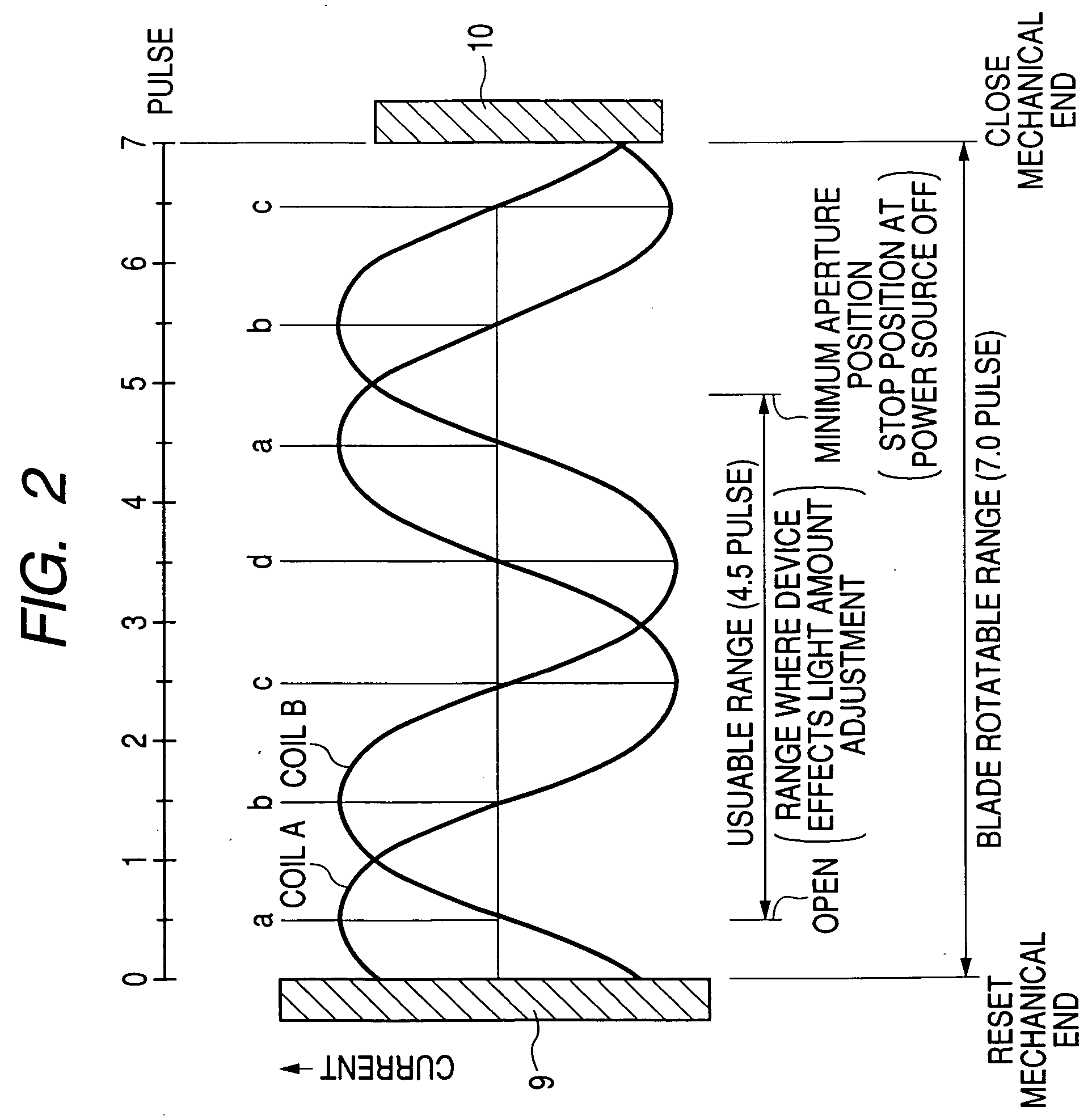
[0042] Referring to FIG. 2, which is used for the description of the first embodiment, and using a flow chart in FIG. 4, a second embodiment of the present invention will be described.
[0043] In the first embodiment, the blades are stopped at the minimum aperture position, which is the end portion of the usable range as a camera, when the power source is turned OFF. However, in the second embodiment, it is assumed that the blades are stopped at the end portion of the blade rotatable range (at the close mechanical end). FIG. 4 is a flow chart showing this operation. In FIG. 4, first, it is judged whether or not the power source of the camera is turned OFF (#41). If it is judged that the power source is turned OFF, the blades are driven to the close mechanical end (the pulse position for 7.0 in FIG. 2) (#42). At this time, the blades are driven for some more pulses after being brought into abutment with the close mechanical end, thereby reliably bringing the blades into abutment with ...
PUM
 Abstract
Description
Claims
Application Information
 - R&D Engineer
- R&D Manager
- IP Professional
- Industry Leading Data Capabilities
- Powerful AI technology
- Patent DNA Extraction
Browse by: Latest US Patents, China's latest patents, Technical Efficacy Thesaurus, Application Domain, Technology Topic.
© 2024 PatSnap. All rights reserved.Legal|Privacy policy|Modern Slavery Act Transparency Statement|Sitemap