Wireless power transfer system and wireless power transfer method

Active Publication Date: 2017-01-19
FUJITSU LTD
View PDF2 Cites 9 Cited by
  • Summary
  • Abstract
  • Description
  • Claims
  • Application Information

AI Technical Summary

Benefits of technology

[0010]By producing a rotating magnetic field as illustrated in FIG. 1, the transfer efficiency can be made insensitive to the angle of the plane of the receiver coil. However, the permissible di

Problems solved by technology

However, the permissible directions of the normal vector of the receiver coil are limited within a two-dimensio

Method used


Image

  • Wireless power transfer system and wireless power transfer method
  • Wireless power transfer system and wireless power transfer method
  • Wireless power transfer system and wireless power transfer method

Examples


first embodiment

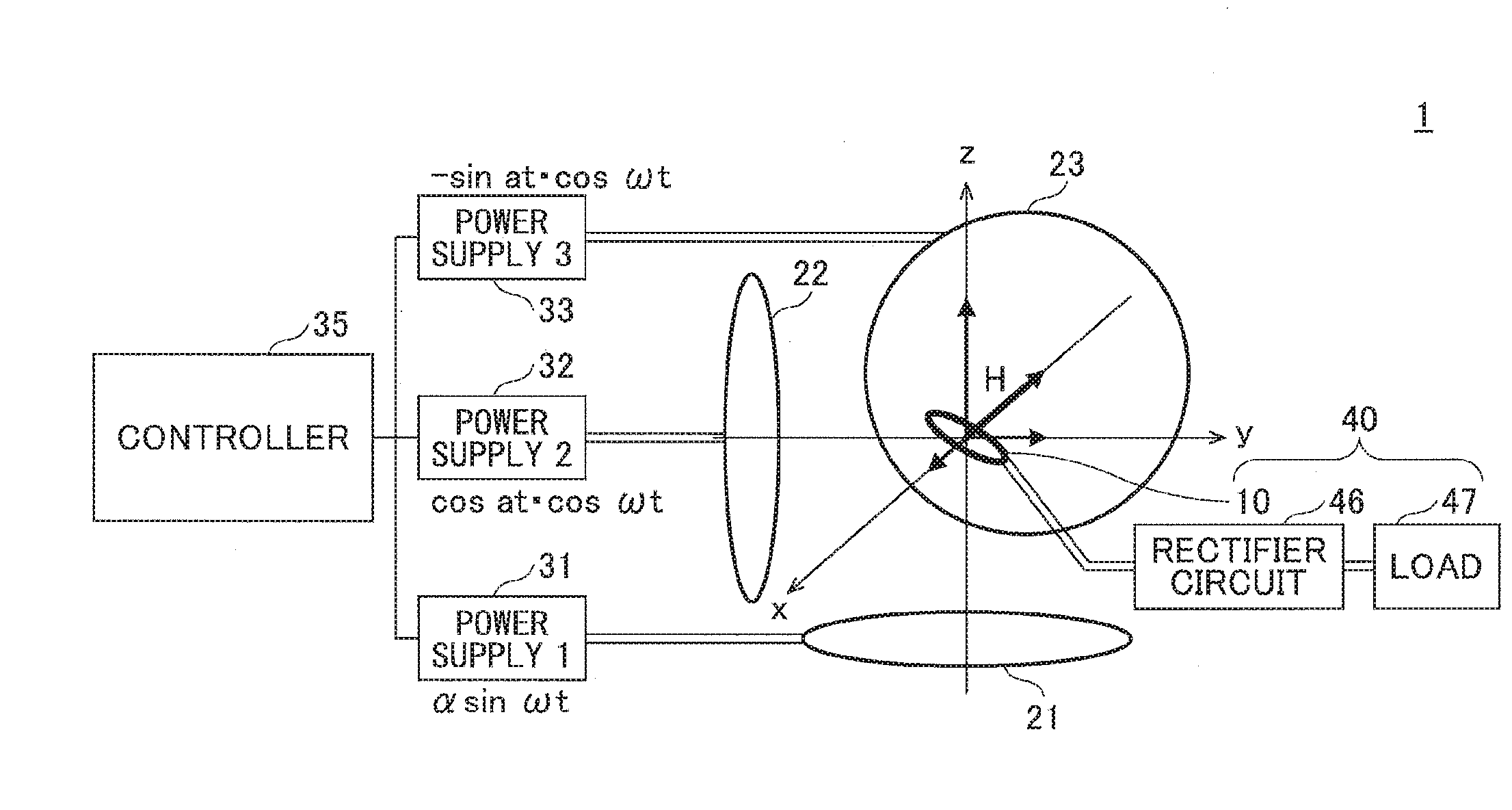
[0030]FIG. 3 illustrates a synthetic magnetic field produced using three transmit coils 21, 22 and 23. The transmitter coil 21 is arranged such that the normal vector n21 points the z direction, which coil generates a magnetic field H21. The transmitter coil 22 is arranged such that the normal vector n22 points the y direction, which coil generates a magnetic field H22. The transmitter coil 23 is arranged such that the normal vector n23 points the x direction, which coil generates magnetic field H23.

[0031]When transferring energy by electromagnetic induction, electric current flows in a receiver coil 10 by electromotive force when magnetic field fluxes represented by a synthetic magnetic field vector H generated by the magnetic fields H21, H21 and H23 penetrate the plane of the receiver coil 10. However, when the synthetic magnetic field vector H becomes parallel to the plane of the receiver coil 10, electric energy cannot be transferred to the receiver coil. Similarly, with magneti...

second embodiment

[0043]In the first embodiment, the synthetic magnetic field vector H rotating in a plane (e.g., in the y-z plane) is further rotated about an axis of rotation (e.g., about the z-axis) perpendicular to the normal vector nH1 of the plane of rotation of the synthetic magnetic field vector H. The oscillating power induced in the receiver coil 10 is rectified as it is and converted into DC power.

[0044]As long as, in the above-explained example, the normal vector to the plane of receiver coil 10 resides in the x-y plane (perpendicular to the z-axis serving as the axis of rotation of the normal vector nH1), the received power does not depend on the azimuth angle or the orientation of the receiver coil 10.

[0045]However, when the normal to the plane of the receiver coil 10 tilts toward the z direction, the received power level changes depending on the z component of the synthetic magnetic field. This will be explained in more detail, referring to FIG. 5A and FIG. 5B.

[0046]As illustrated in F...


PUM


Abstract

A wireless power transfer system includes a first transmitter coil, a second transmitter coil and a third transmitter coil arranged such that normal directions to planes of the first, the second and the third transmitter coils are orthogonal to each other in a three-dimensional space, and a controller that controls electric currents supplied to the first, the second and the third transmitter coils such that a synthetic magnetic field vector produced by the first, the second and the third transmitter coils rotates in a plane of rotation at a first angular frequency “ω”, and that a normal vector to the plane of rotation rotates about an axis of rotation perpendicular to the normal vector at a second angular frequency “a” equal to or smaller than the first angular frequency (a≦ω).

Description

CROSS REFERENCE TO RELATED APPLICATIONS[0001]This application is a continuation application filed under 35 U.S.C. 111(a) claiming benefit of priority of PCT International Application No. PCT / JP2014 / 059444 filed Mar. 31, 2014 and designating the United States, which is incorporated herein by reference in its entirety.FIELD[0002]The present invention relates to a wireless power transfer system and a wireless power transfer method.BACKGROUND[0003]In recent years, wireless power transfer technique has been attracting attention, which technique allows electric power or energy to be transferred without using physical wires or cables. In transferring power of several watts or more to a distance of several centimeter to several tens centimeter, electromagnetic induction or coupling is typically used by providing coils in a power transmitter and a power receiver. Especially, power transfer technique making use of magnetic resonance is highly expected to wirelessly supply electric power to mu...

Claims


Application Information

Patent Timeline
IPC IPC(8): H02J50/12H01F38/14
CPCH01F38/14H02J50/12H02J50/005H02J50/10H02J50/90
Inventor OSHIMA, HIROTAKAOZAKI, KAZUYUKI
Owner FUJITSU LTD
Why Eureka
Try Eureka