Separable tilting device

Inactive Publication Date: 2017-01-26
NIEN MADE ENTERPRISE CO LTD
View PDF0 Cites 12 Cited by
  • Summary
  • Abstract
  • Description
  • Claims
  • Application Information

AI Technical Summary

Benefits of technology

[0007]In view of the reasons mentioned above, the primary objective of the present invention is to provide a sep

Problems solved by technology

In other words, an end user may not be able to assemble these components on his own; instead, an end user could only adjust the tilt angle of the slats through such hook or rod.
Also, the worm extends out of a

Method used


Image

  • Separable tilting device
  • Separable tilting device
  • Separable tilting device

Examples


Embodiment Construction

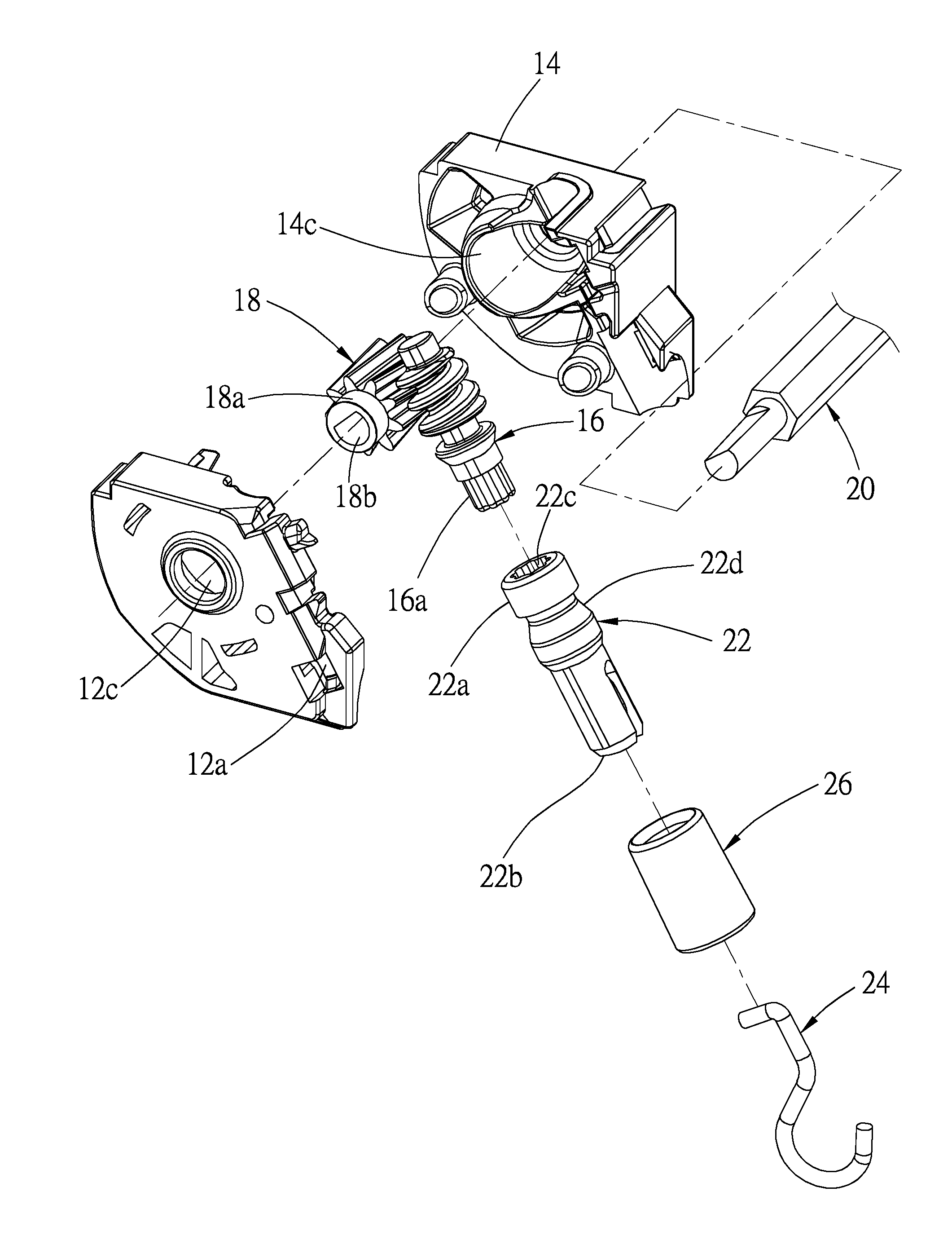
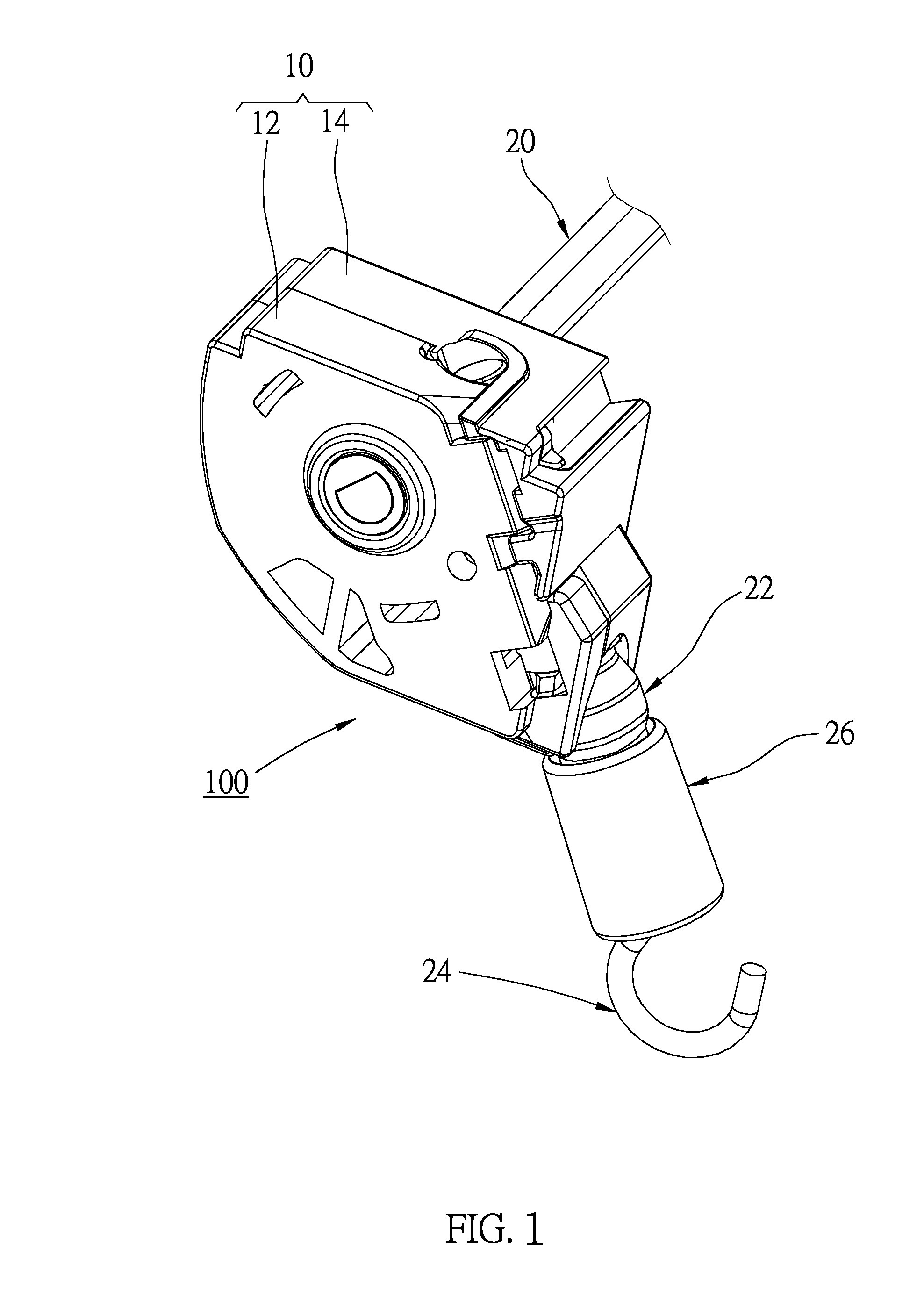
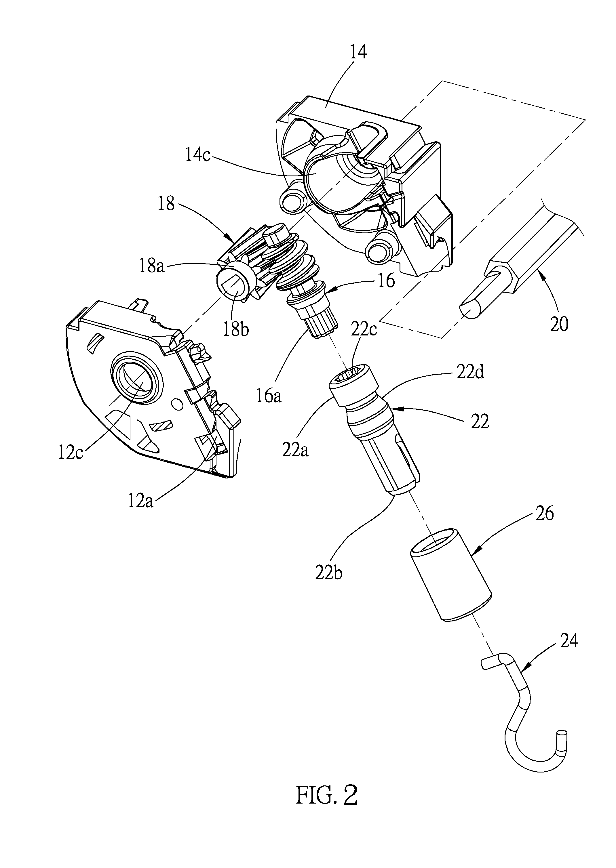
[0027]As shown in FIG. 1 to FIG. 4, a separable tilting device 100 of a first embodiment of the present invention is installed in a headrail T of a window covering. The separable tilting device 100 includes a case 10, a first driving member, a second driving member, a connector 22, a hook 24, and a sleeve 26.

[0028]The case 10 includes two sub-cases 12, 14 made of plastic, wherein the sub-cases are combined to form a chamber therebetween. A first opening 12a (14a), a stop member 12b (14b), and a lateral bore 12c (14c) are integrally formed on each of the sub-cases, wherein the first opening 12a (14a) and the lateral bore 12c (14c) communicate with the chamber. The stop member 12b (14b) is integrally connected to a peripheral edge of the first opening 12a (14a), with an end thereof extending toward the chamber. In addition, a second opening 10a is formed on a bottom of the combined sub-cases 12, 14, wherein the second opening 10a also communicates with the chamber.

[0029]The first driv...


PUM


Abstract

A separable tilting device includes a case, a first driving member, a second driving member, and a connector. The first driving member and the second driving member are provided in a chamber of the case, and are movable by each other. The connector is connected to the first driving member, wherein the connector has an engaging slot. An end of a stop member of the case extends into the engaging slot, so that the connector could not be disengaged from the first driving member. An end of the connector is controllable to rotate the first driving member. Whereby, the first driving member and the second driving member are completely hidden inside the case, which prevents the tilting device or slats of a window covering from being damaged.

Description

[0001]The current application claims a foreign priority to application number 201520544088.3 filed on Jul. 24, 2015 in China.BACKGROUND OF THE INVENTION[0002]1. Technical Field[0003]The present invention generally relates to structures of window coverings, and more particularly to a separable tilting device, which could be installed on one's own to prevent the slats from being deformed.[0004]2. Description of Related Art[0005]Titling devices are commonly used in window coverings to control and adjust the tilt angle of slats, and therefore to change the amount of light which could pass through. A conventional tilting device mainly includes a worm gear and a worm. As disclosed in U.S. Pat. No. 4,406,319, titled “Venetian blind drive control”, and U.S. Pat. No. 4,947,921, titled “Lift lock and tilt device for a Venetian blind”, the worm gear is rotatably provided in a case, which is provided in a headrail of a window covering. An end of the worm engages with the worm gear, and is locat...

Claims


Application Information

Patent Timeline
IPC IPC(8): E06B9/307E06B9/32F16H1/16
CPCE06B9/307E06B2009/285E06B9/32F16H1/16
Inventor NIEN, CHAO-HUNGCHANG, CHIH-YAOYUAN, WEI-XUE
Owner NIEN MADE ENTERPRISE CO LTD
Why Eureka
Try Eureka