Handling device

a technology of handling device and burner, which is applied in the direction of mechanical equipment, machines/engines, light and heating equipment, etc., can solve the problems of high cost of robotic devices of the mentioned type, time-consuming and cumbersome installation of such a robotic device prior to the assembly or disassembly of a burner, etc., and achieves the effect of simple and inexpensive construction and easy handling

Active Publication Date: 2017-02-02
SIEMENS ENERGY GLOBAL GMBH & CO KG
View PDF8 Cites 6 Cited by
  • Summary
  • Abstract
  • Description
  • Claims
  • Application Information

AI Technical Summary

Benefits of technology

[0005]An aspect relates to a handling device of the above-mentioned type, which has a simple and inexpensive construction and is easy to handle.

Problems solved by technology

However, the installation of such a robotic device prior to the assembly or disassembly of a burner is very time-consuming and cumbersome.
Moreover, robotic devices of the mentioned type are very expensive.

Method used


Image

  • Handling device
  • Handling device
  • Handling device

Examples


Embodiment Construction

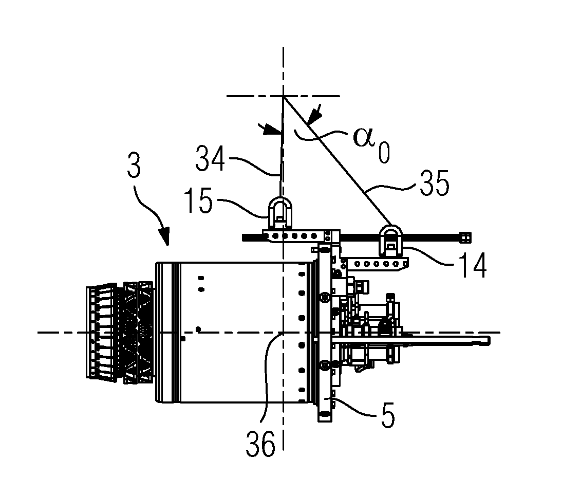
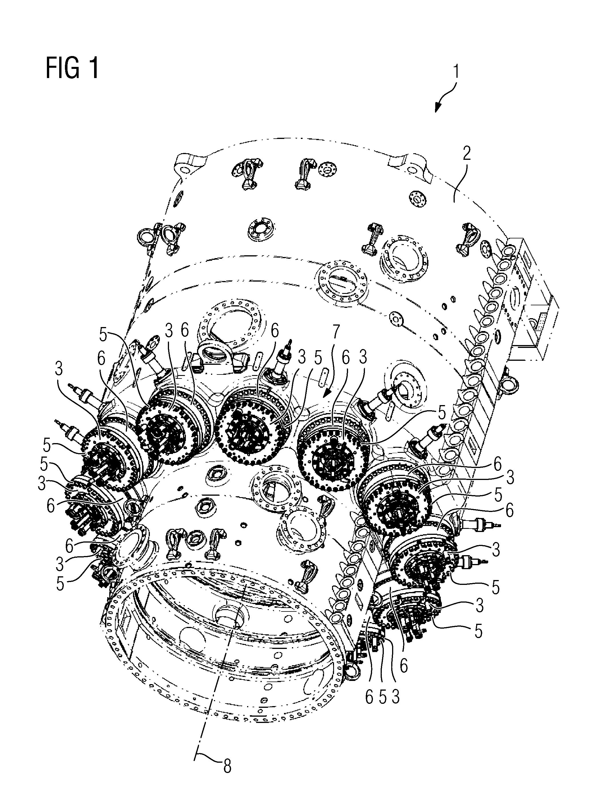
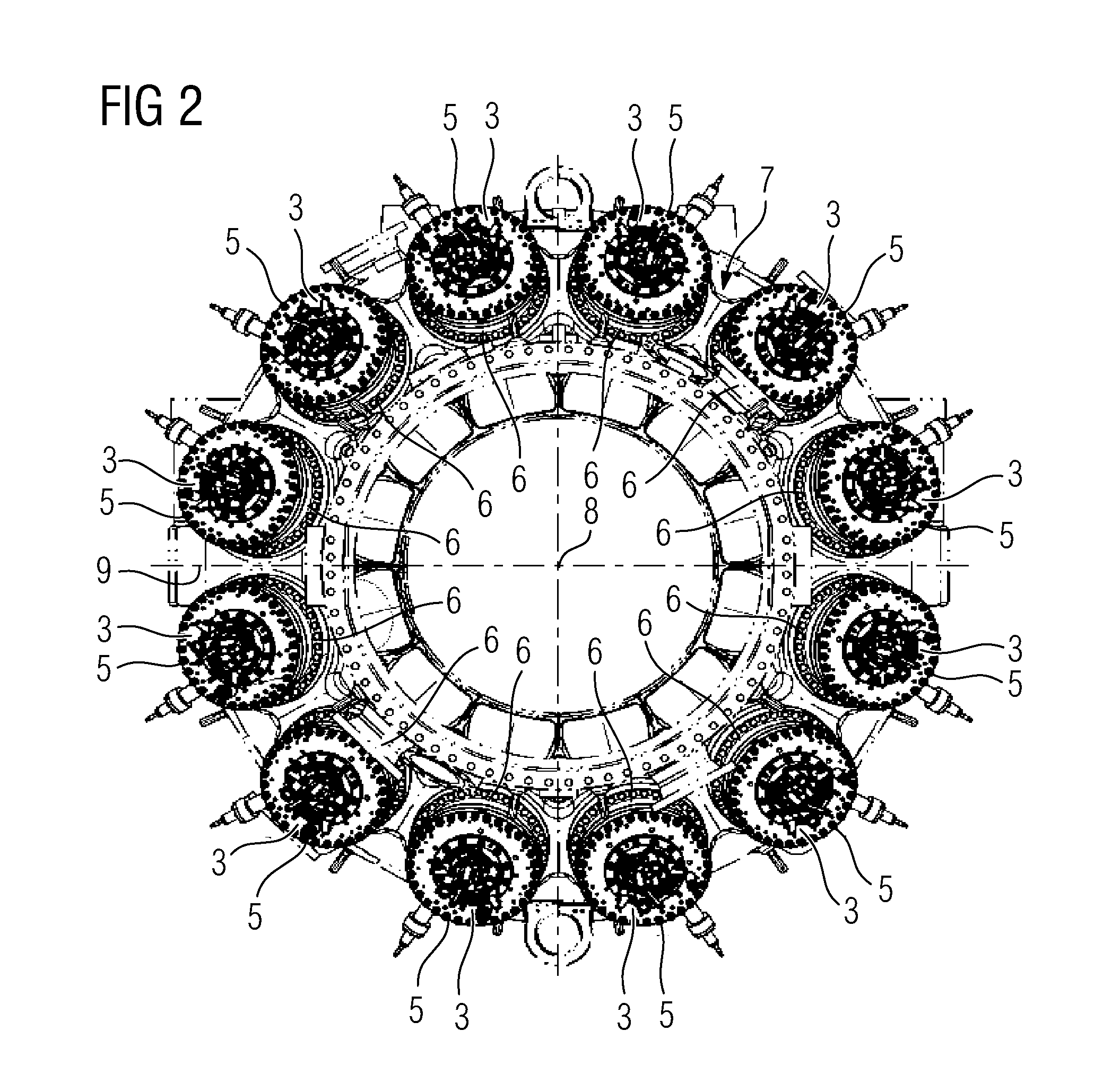
[0031]FIGS. 1 and 2 shows a part of an exemplary stationary gas turbine 1, which is known in prior art. The stationary gas turbine 1 comprises a turbine housing 2 and twelve burners 3, which are inserted in allocated burner receiving openings 4 of the turbine housing 2 at positions P1 to P12 and are screwed at flange portions 5 provided at the rear end of each burner 3 with essentially cylindrical shells 6 attached to the turbine housing 2. The burner receiving openings 4 are arranged at equal intervals along the perimeter of a ring surface 7 of the turbine housing 2, which is inclined with respect to a longitudinal axis 8 of the turbine housing 2. Accordingly, the burner receiving openings 4 and the burners 3 inserted therein have a plurality of different orientations. For example, the respective inclination angles with respect to a horizontal plane 9 of the burners 3 at the positions P1 and P12 are different to the respective inclination angles of the burners 3 at the positions P2...


PUM


Abstract

A handling device is provided for handling a burner of a stationary gas turbine during assembly and disassembly, including a base body having at least one contact surface designed to contact a rear end surface of a burner, fixing means for fixing the base body to the rear end surface of the burner, and two arms fixed to and protruding from the base body to different sides of the contact surface, wherein each arm is provided with receiving means, which are designed for removably receiving a fixing component of a lifting appliance and which are spaced apart from each other in the longitudinal direction of a burner during its handling.

Description

CROSS-REFERENCE TO RELATED APPLICATIONS[0001]This application claims priority to PCT Application No. PCT / EP2014 / 050404, having a filing date of Jan. 12, 2015, based off of EP Application No. 14154585.5 having a filing date of Feb. 11, 2014, the entire contents of which are hereby incorporated by reference.FIELD OF TECHNOLOGY[0002]The following relates to a handling device for handling a burner of a stationary gas turbine during assembly and disassembly.BACKGROUND[0003]Stationary gas turbines are known in prior art. They normally comprise a plurality of burners, which are inserted in burner receiving openings of the turbine housing. The receiving openings are arranged at equal intervals along the perimeter of a ring surface, which is inclined with respect to the longitudinal axis of the turbine housing. Accordingly, the burner receiving openings have a plurality of different orientations demanding a high positioning flexibility of a handling device, which is used for handling the hea...

Claims


Application Information

Patent Timeline
Patent Type & Authority Applications(United States)
IPC IPC(8): F01D25/28F23R3/60F02C7/264
CPCF01D25/285F02C7/264F23R3/60F23R2900/00019F05D2230/68F05D2230/70F05D2220/32
Inventor ALVAREZ, ALBERTO
Owner SIEMENS ENERGY GLOBAL GMBH & CO KG
Why Eureka
Try Eureka