Container for Dispensing Liquid Doses

a container and liquid technology, applied in the field of liquid or beverage containers, can solve the problems of affecting the comfort of consumers, and reducing the temperature of beverages, etc., and achieve the effect of simple and inexpensive construction

Active Publication Date: 2010-08-05
DRUYAN EUGENE
View PDF41 Cites 3 Cited by
  • Summary
  • Abstract
  • Description
  • Claims
  • Application Information

AI Technical Summary

Benefits of technology

[0011]The present invention advantageously provides a spill resistant container for dispensing liquid doses that is of relatively simple and inexpensive construction as compared to devices of similar functionality of the prior art.

Problems solved by technology

A hot beverage, such as coffee, consumed at a temperature of greater than 80 degree Celsius has the potential to scald or otherwise damage the mouth and lips of a consumer.
Unfortunately, upon cooling a beverage to a comfortable consumption temperature, the beverage temperature quickly decreases until a hot beverage is below the optimal consumption temperature.
A similar situation exists with cold beverages that have the potential to irritate sensitive dental structures or chill portions of the digestive tract to cause temporary cramps or pain.
Sometimes, when liquids enter the windpipe of a person who has dysphagia, coughing or throat clearing cannot remove it.
Liquid that stays in the windpipe may enter the lungs and create a chance for harmful bacteria to grow.
A serious infection (aspiration pneumonia) can result.
Many currently available children training cups are criticized for not being properly designed to train children to sip because of the valves used in such cups.
While the valves prevent spillage, they make the children suck the beverage instead of sip it, which defeats the purpose of the training cup.
In addition, many cups have a hard spout that increases risk of injury to the children's mouth and teeth when they carry the cup around.
Known travel mug designs typically include complex structures of valves and / or pump components and do not provide sip or volume dosing.

Method used


Image

  • Container for Dispensing Liquid Doses
  • Container for Dispensing Liquid Doses
  • Container for Dispensing Liquid Doses

Examples


Embodiment Construction

[0031]The description, which follows, and the embodiments described therein, is provided by way of illustration of an example, or examples of particular embodiments of principles and aspects of the present invention. These examples are provided for the purposes of explanation, and not of limitation, of those principles and of the invention.

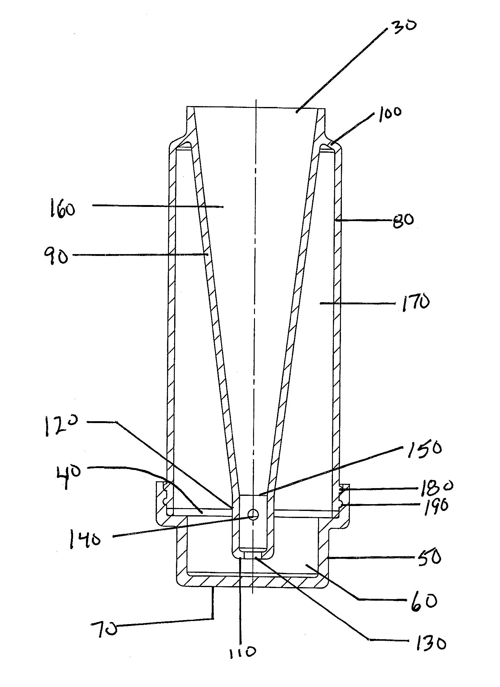
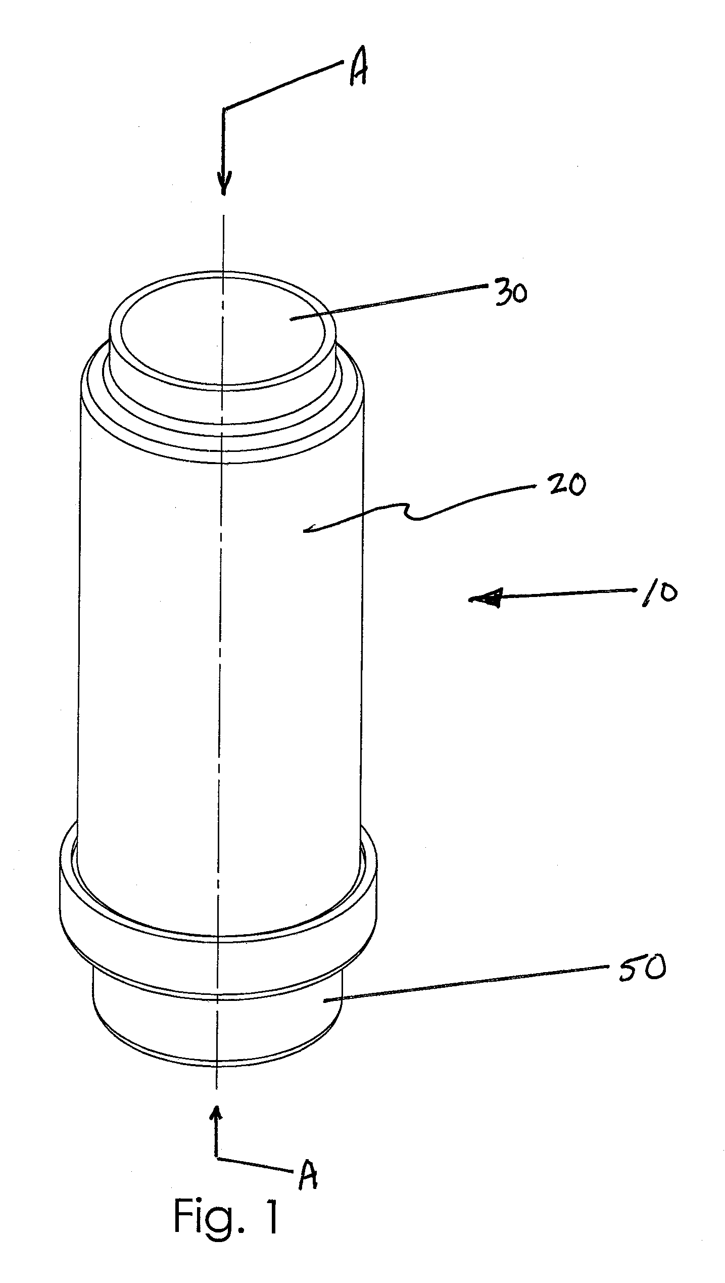
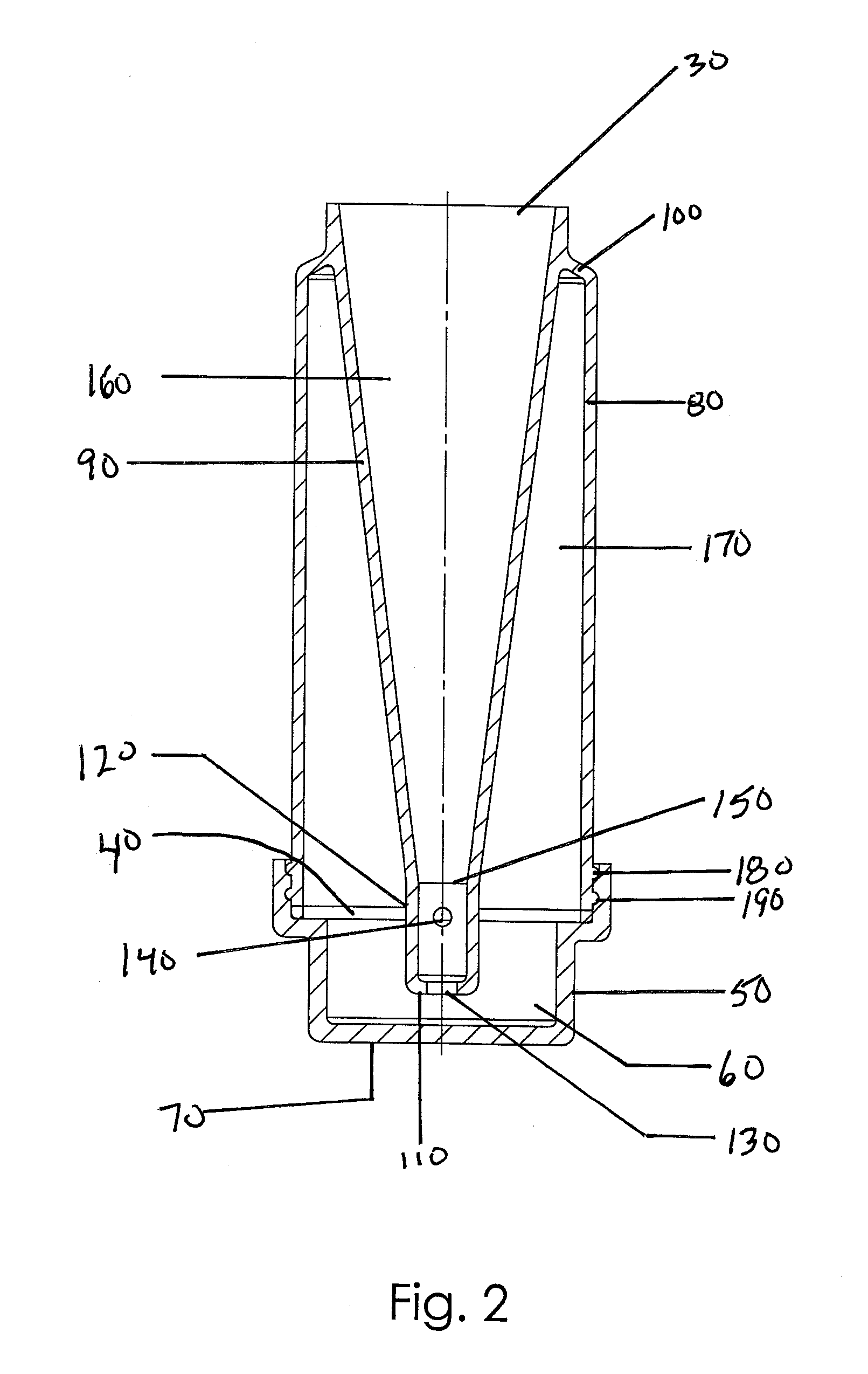
[0032]Referring to FIGS. 1, 2, and 3 a container 10, shown in a first or upright position, includes a body 20 of generally hollow form about a vertical axis with an open top end 30 and open bottom end 40 and a base cap 50 constructed to define a cavity 60 for holding liquid and to sealingly engage with body 20. As shown, the cap 50 includes a generally flat base 70. Optionally, a seal 55 may also be used.

[0033]The body 20 includes an outer side wall 80 and an inner side wall 90. The inner side wall 90 is shown having a generally frusto-conical shape but may equally be generally cylindrically or substantially cone shaped. The inner side wall 90 is ...


PUM


Abstract

The present invention relates to spill resistant container for dispensing liquid doses wherein the container includes a body of generally hollow form about a centre vertical axis with open ends, comprising: an liquid deposit chamber having an open first end and an opposing closed second end, a liquid withdrawal chamber having a open first end and an opposing closed second end, one or more apertures between said deposit and withdrawal chambers adapted to selectively permit liquid communication in controlled doses from the liquid deposit chamber to the liquid withdrawal chamber, a detachable base cap having a cavity in liquid communication with the liquid deposit and withdrawal chambers.

Description

FIELD OF THE INVENTION[0001]The present invention relates to the field of vessels or containers for liquids or beverages. More specifically, the present invention relates to the field of spill resistant, controlled sip or volume dosing containers, including containers which moderate the temperature of a beverage portion before withdrawal from the container.BACKGROUND OF THE INVENTION[0002]A spill resistant drinking container is highly desirable in applications where there is an increased probability of spillage during drinking, such as in hospitals and nursing homes with debilitated patients, training cups for children, and in moving vehicles such as airplanes, boats, ships, trains and automobiles.[0003]Volume dosing is desirable in containers for hot beverages. A hot beverage, such as coffee, consumed at a temperature of greater than 80 degree Celsius has the potential to scald or otherwise damage the mouth and lips of a consumer. Solutions to this problem have included stirring th...

Claims


Application Information

Patent Timeline
Patent Type & Authority Applications(United States)
IPC IPC(8): B65D25/04B67D7/30
CPCA47G19/2266G01F15/14G01F11/268G01F11/262
Inventor DRUYAN, EUGENE
Owner DRUYAN EUGENE
Why Eureka
Try Eureka