Lumination device

A lighting equipment and image technology, applied in lighting and heating equipment, lighting applications, mechanical equipment, etc., can solve the problems of large size, expensive, etc., and achieve the effect of small size

Inactive Publication Date: 2006-11-22
PHILIPS LIGHTING HOLDING BV
View PDF1 Cites 4 Cited by
  • Summary
  • Abstract
  • Description
  • Claims
  • Application Information

AI Technical Summary

Problems solved by technology

[0006] Lighting devices of the type described above have a serious disadvantage
They are usually of very large size, quite heavy and quit

Method used


Image

  • Lumination device
  • Lumination device
  • Lumination device

Examples


Embodiment Construction

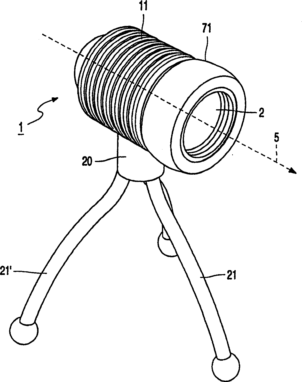
[0036] figure 1 is a schematic perspective view of an embodiment of an illumination device for projecting images by light beams according to the present invention. The lighting device comprises a housing 1 with a light emission window 2 arranged in an adjustment element 71 which is movable relative to the housing 1 . In operation, the lighting device emits a beam of light along the longitudinal axis 5 . The housing is provided with cooling fins 11 and is supported by a bracket 20, which in this example rests on three flexible legs 21, 21'. The lighting device can be hung or equipped with a light cap.

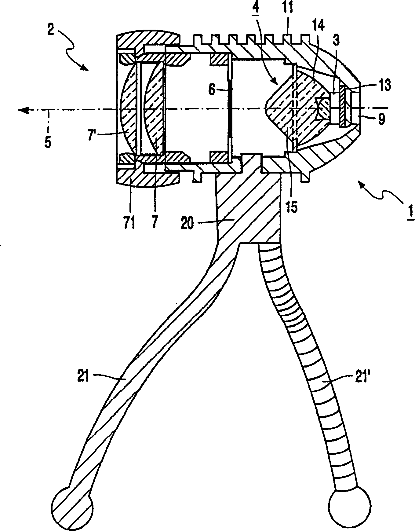
[0037] Figure 2A Schematically shows a partially sectioned and partially perspective according to the present invention such as figure 1Cutaway view of the lighting device shown. The housing 1 has cooling fins 11 and is supported by brackets 20 resting on flexible legs 21, 21'. The housing 1 also includes an opening 9 allowing the passage of electrical connection cables. ...


PUM


Abstract

A lighting device for projecting images comprises a housing (1) with a light emission window (2). The housing (1) has a light source (3), an optical system (4) for directing the light beam from the light source (3) along the longitudinal axis (5), and a The image forming surface (6) in the vertical direction. According to the invention, the light source is an LED, and the optical system (4) includes a collimating element (14) for collimating the light emitted by the LED. Preferably the lighting device comprises only one LED, having a luminous flux of at least 5 lm during operation. Preferably, the housing (1) also includes a focusing lens (15) for focusing the collimated light beam emitted by the collimating element (14) on the image forming surface (6), and preferably includes a Projection lenses (7, 7') for image forming the image of the surface (6). Preferably parts of the collimating element exhibit total internal reflection. The lighting device according to the present invention is a lighting device with small size, light weight, low energy consumption and low maintenance cost.

Description

technical field [0001] The present invention relates to a lighting device for projecting images by light beams, comprising [0002] a housing with a light emission window containing a light source and an optical system for directing the radiation emitted by the light source along the longitudinal axis, and [0003] An image forming surface is disposed in the light beam transversely to the longitudinal axis. Background technique [0004] Such lighting devices are known per se. They are used, in particular, in theater lighting such as stage lighting, especially for projecting images or silhouettes onto a stage, screen, background or curtain. Other applications of these lighting devices include projecting signs, text or other images onto building surfaces or pavements, for example in front of shop windows, to attract the attention of potential customers. Dynamic effects are usually provided by setting moving mirrors in the shell. Additionally, the lighting device typically ...

Claims


Application Information

Patent Timeline
IPC IPC(8): G03B23/06F21S8/00G03B15/02F21W131/406F21Y101/02F21S6/00F21S10/00F21V5/00F21V5/04F21V7/00F21V14/06F21V21/06F21V29/00F21V29/76F21Y115/10H01L33/00H01L33/58H01L33/64
CPCF21S6/002F21V5/008F21V5/048F21V7/0091F21V14/06F21V21/06F21W2131/406G03B21/2033G03B21/208G02B27/0944G02B27/425G02B19/0028G02B19/0061F21V29/767F21Y2115/10F21V29/74
Inventor L·拉默斯J·P·M·安瑟姆斯A·J·M·范赫斯T·F·M·M·马斯
Owner PHILIPS LIGHTING HOLDING BV
Why Eureka
Try Eureka