
Mold clamping apparatus of injection molding machine and method of adjusting effective length of tie bar

a technology of injection molding machine and clamping apparatus, which is applied in the direction of auxillary shaping apparatus, manufacturing tools, food shaping, etc., can solve the problems of increasing the cost of manufacturing the mold clamping apparatus, the first method has the following problems, and the thickness variance is small, and the effect of excellent molded products

Active Publication Date: 2006-12-21
JAPAN STEEL WORKS LTD
View PDF7 Cites 3 Cited by
  • Summary
  • Abstract
  • Description
  • Claims
  • Application Information

AI Technical Summary

Benefits of technology

[0019] Therefore, it is object of the invention to provide a mold clamping unit of an injection molding machine, which is inexpensive and is capable of adjusting the effective lengths of the tie bars in a short time, even in the process of the molding operation, and a method of adjusting the effective lengths of the tie bars.
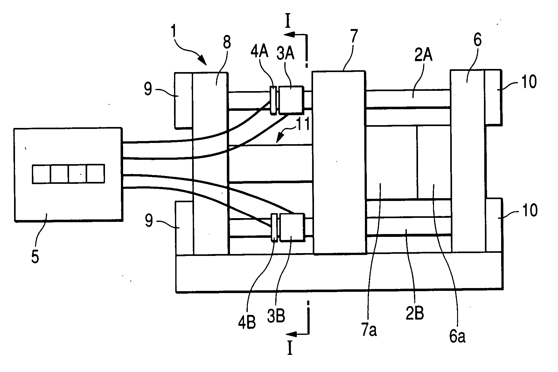
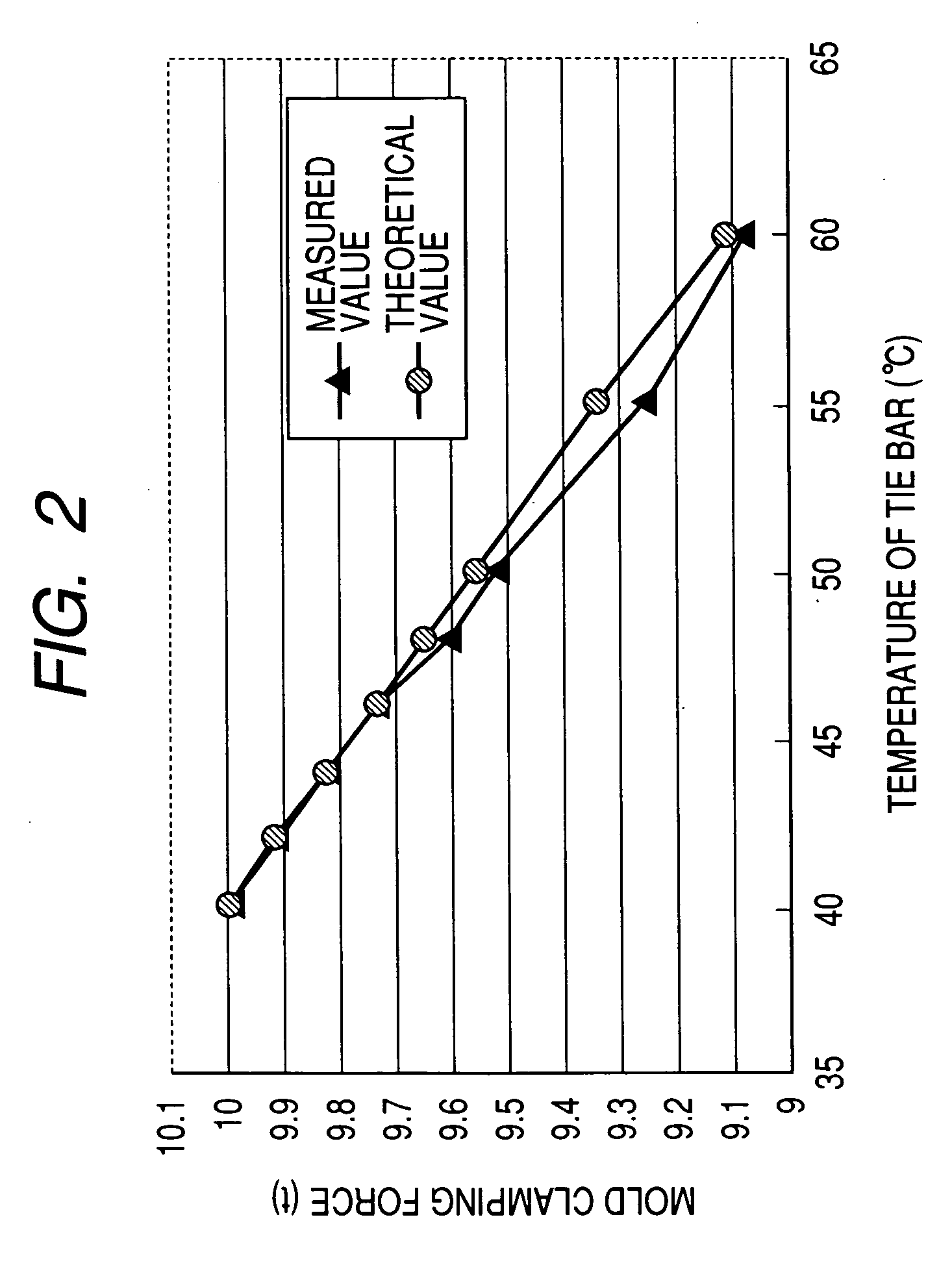
[0022] According to the invention, since the temperature of each of the tie bars is individually adjusted, the effective lengths of the tie bars themselves are varied due to the thermal expansion depending on the heated temperature. In this way, the effective length of each of the tie bars is adjusted individually such that the balance of the extended amount of each of the tie bars when the mold clamping force is generated by closing the mold, and furthermore the balance of the mold clamping force acting on the molds can be adjusted. As a result, it is possible to manufacture an excellent molded product of which thickness variance is small.
[0023] Therefore, according to the invention, it is possible to adjust the effective lengths of the tie bars by a simple and inexpensive construction of the heaters, the sensors, and the temperature adjustor. Furthermore, it is possible to perform the adjustment of the effective lengths of the tie bars without disassembling the mold clamping apparatus, and furthermore it is possible to perform the adjustment during the time of the molding operation. Accordingly, according to the invention, it is possible to perform the adjustment of the effective lengths of the tie bars in a short time.
[0024] As described above, according to the present invention, it is possible to adjust the effective lengths of the tie bars, even in the process of the molding operation.

Problems solved by technology

However, the first method has following problems.
(1) The operation of the injection molding machine needs to be stopped to adjust the effective lengths of the tie bars, and molded products cannot be manufactured during the adjustment.
(2) Since a unit (such as servomotor) for driving each of the die height adjusting nuts is separately required, cost of manufacturing the mold clamping apparatus increases remarkably, whereby it is not practical.
(3) Since the adjustment is rarely completed by performing the adjusting operation only one time, and it is needed to repeat many times the operation and the stoppage of the injection molding apparatus until the adjusting operation is completed, the adjusting operation takes labor and long time.
(4) Since the product molded through a test during the adjustment cannot be shipped as a product and should be discarded, as the adjusting operation is repeated in many times, the amount of wasted material increases.
Furthermore, the second method has following problems.
(1) The operation of the injection molding machine needs to be stopped to adjust the effective lengths of the tie bars, and molded products cannot be manufactured during the adjustment.
Therefore, the adjusting operation takes labor and long time.
(4) Since the product molded through a test during the adjustment cannot be shipped as a product and should be discarded, as the adjusting operation is repeated in many times, the amount of wasted material increases.

Method used


Image

  • Mold clamping apparatus of injection molding machine and method of adjusting effective length of tie bar
  • Mold clamping apparatus of injection molding machine and method of adjusting effective length of tie bar
  • Mold clamping apparatus of injection molding machine and method of adjusting effective length of tie bar

Examples


application experiment

[0050] (Application Experiment)

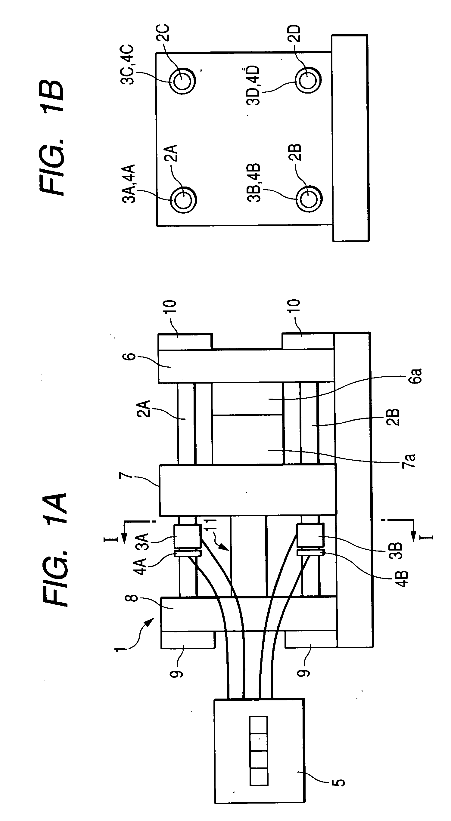
[0051] (1) FIG. 3A shows the substrate thickness distribution on the periphery (R=58 mm) of the DVD at the initially set temperature (the initially set temperature of the every tie bar is 40° C.). The variance of the substrate thickness (difference between the maximum and minimum values of the substrate thickness) in the initially set state is 8.2 μm. FIG. 3B is a view schematically illustrating the positional relationship between the DVD molded in the molds 6a and 7a and each of the tie bars 2A to 2D, when the molds 6a and 7a are seen from the I-I direction of FIG. 1A. Furthermore, angles illustrated on the horizontal axis of FIG. 3A correspond to angles illustrated in FIG. 3B.

[0052] (2) From the result shown in FIG. 3, since it can be understood that the substrate thickness of the DVD becomes thin at the upper side thereof, the temperature of the temperature adjusting range of the upper tie bars 2A and 2B was varied to 45° C. The substrate thickness...


PUM

PropertyMeasurementUnit
lengthaaaaaaaaaa
temperatureaaaaaaaaaa
lengthaaaaaaaaaa

Abstract

A mold clamping apparatus of an injection molding machine, which includes a fixed platen to which a fixed-side mold is attached, a mold clamping housing, a plurality of tie bars provided between the fixed platen and the mold clamping housing and a movable platen to which a moving-side mold is attached and which is capable of moving with respect to the fixed platen along the tie bars. The mold clamping apparatus includes heaters for heating the tie bars and sensors for sensing the temperatures of portions heated by the heaters, and the heaters and the sensors are provided to each of the plurality of tie bars. The mold clamping apparatus includes a temperature adjustor, which is connected to the heaters and the sensors and controls the temperatures of the heated portions of the tie bars.

Description

[0001] This application is based on Japanese Patent Application No. 2005-178146, which is incorporated herein by reference. BACKGROUND OF THE INVENTION [0002] 1. Field of the Invention [0003] The present invention relates to a mold clamping apparatus of an injection molding machine and to a method of adjusting effective lengths of tie bars. [0004] 2. Description of the Related Art [0005] A mold clamping apparatus shown in FIG. 6 has been known as a mold clamping apparatus provided to an injection molding machine. FIG. 6 is a view schematically showing a related molding clamping apparatus, in which FIG. 6A is a front view thereof, and FIG. 6B is a sectional view taken along a line XI-XI of FIG. 6A. [0006] The mold clamping apparatus 101 shown in FIG. 6 includes a fixed platen 106 to which a fixed-side mold 106a is attached, a movable platen 107 to which a moving-side mold 107a is attached and which is capable of moving with respect to the fixed platen 106, and a mold clamping housing...

Claims


Application Information

Patent Timeline
Patent Type & Authority Applications(United States)
IPC IPC(8): B29C45/66
CPCB29C45/17B29C45/7653B29C45/1751
Inventor MORII, AKIRA
Owner JAPAN STEEL WORKS LTD
Learn More