Interactive projector and method of correcting z-coordinate of the same

a projector and projector technology, applied in the field of interactive projectors, can solve the problem that the accuracy of contact detection is not necessarily sufficien

Active Publication Date: 2017-02-02
SEIKO EPSON CORP
View PDF3 Cites 2 Cited by
  • Summary
  • Abstract
  • Description
  • Claims
  • Application Information

AI Technical Summary

Benefits of technology

[0009]According to the interactive projector, since at least one of the Z-coordinate value of the screen surface, the Z-coordinate value of the pointing element, and the difference threshold value is corrected based on the history of the Z-coordinate value of the pointing element, even in the case in which a shift occurs in either of the Z-coordinate value of the pointing element and the Z-coordinate value of the screen surface, the shift can be corrected, and it becomes possible to accurately detect presence or absence of the contact of the pointing element with the screen surface.
[0011]According to this configuration, the three-dimensional coordinate value of the pointing element can accurately be detected using the triangulation.
[0013]Since the state in which the pointing element has contact with the screen surface is generally reflected on the histogram of the Z-coordinate values of the pointing element, by arranging that the correction is performed based on the histogram, the detection accuracy of the presence or absence of the contact of the pointing element with the screen surface can be improved.
[0015]Since the magnitude relation between the Z-coordinate value representing the peak of the histogram and the Z-coordinate value of the screen surface represents the shift of the Z coordinate, by arranging that the correction is performed in accordance with the magnitude relation, the detection accuracy of the presence or absence of the contact of the pointing element with the screen surface can be improved.
[0017]Since the magnitude relation between the minimum Z-coordinate value in the history of the Z-coordinate value of the pointing element and the Z-coordinate value of the screen surface represents the shift of the Z coordinate, by arranging that the correction is performed in accordance with the magnitude relation, the detection accuracy of the presence or absence of the contact of the pointing element with the screen surface can be improved.
[0019]It is conceivable that if the Z-direction speed of the pointing element is zero, the pointing element has contact with the screen surface. Therefore, by arranging that the correction is performed based on the history of the Z-coordinate value of the pointing element in the case in which the Z-direction speed of the pointing element is zero, the detection accuracy of the presence or absence of the contact of the pointing element with the screen surface can be improved.

Problems solved by technology

However, in the related art, the accuracy of the contact detection is not necessarily sufficient in some cases, and an improvement in the detection accuracy has been desired.

Method used


Image

  • Interactive projector and method of correcting z-coordinate of the same
  • Interactive projector and method of correcting z-coordinate of the same
  • Interactive projector and method of correcting z-coordinate of the same

Examples


first embodiment

A. First Embodiment

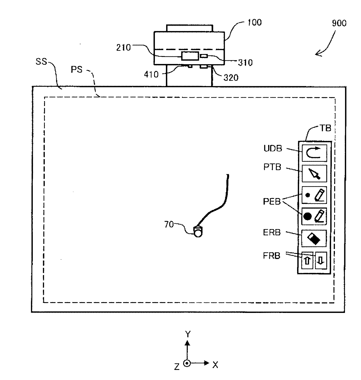
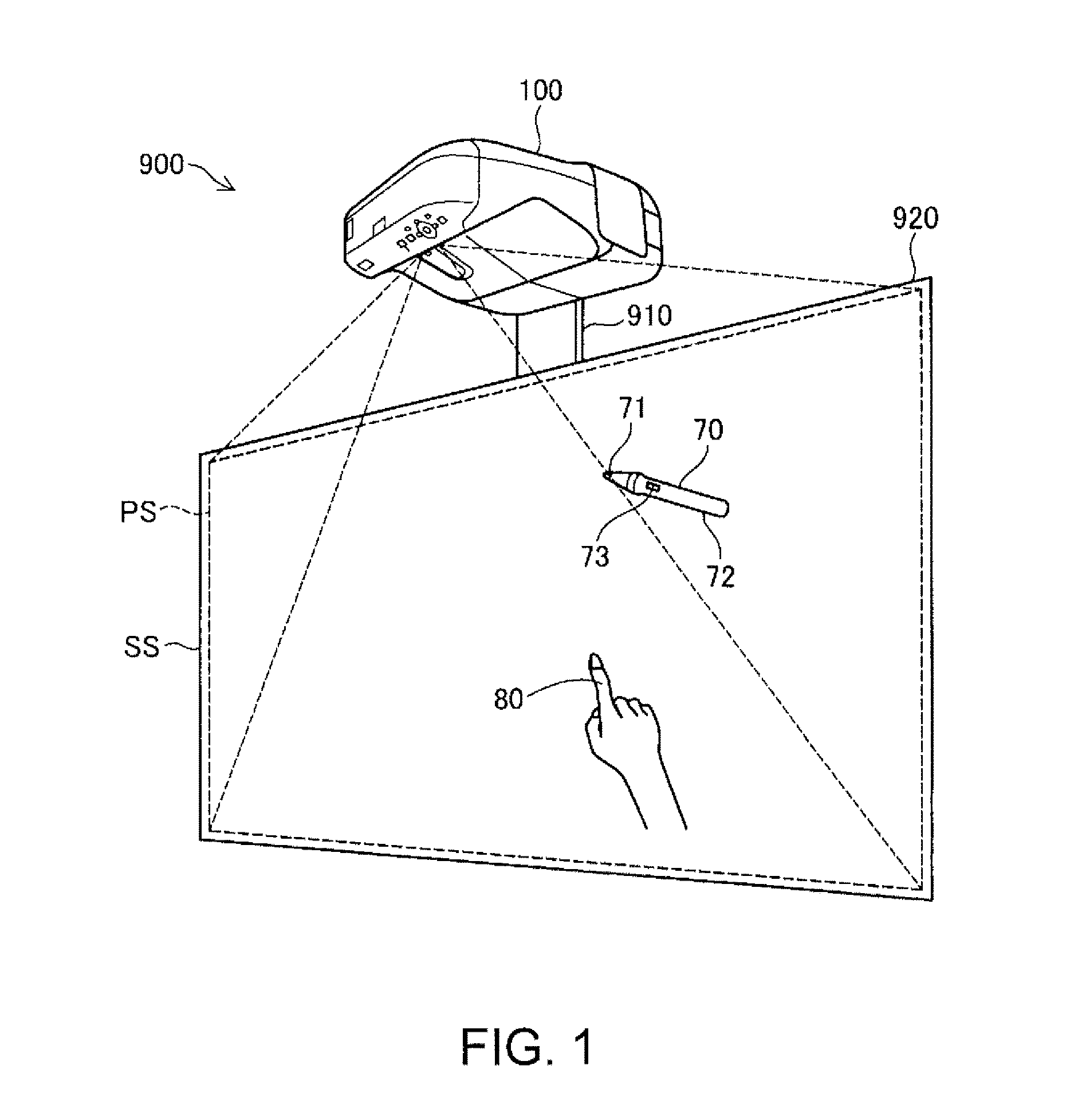
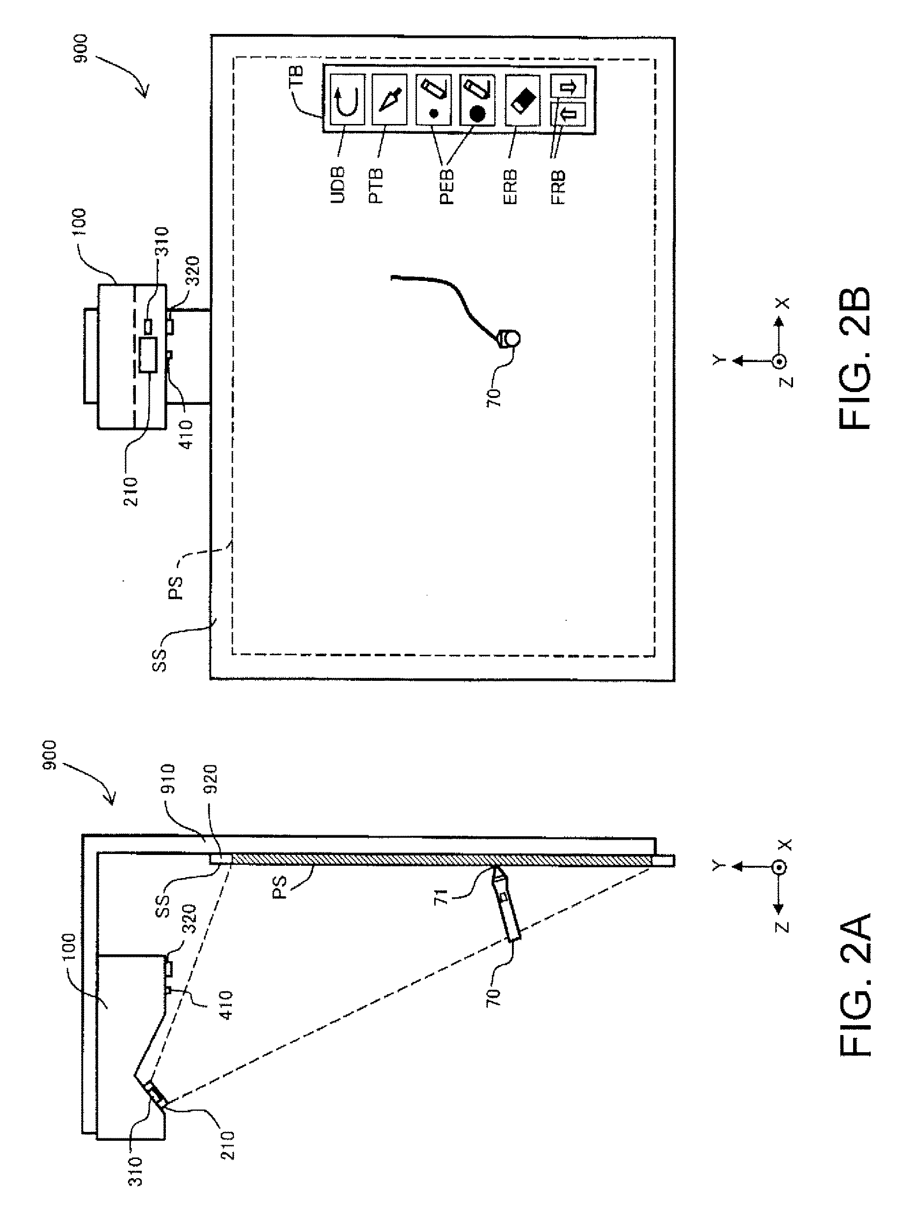
[0031]FIG. 1 is a perspective view of an interactive projection system 900 according to a first embodiment of the invention. The system 900 has an interactive projector 100, a screen plate 920, and a light-emitting pointing element 70. A front surface of the screen plate 920 is used as a projection screen surface SS. The projector 100 is fixed in front of and above the screen plate 920 with a support member 910. It should be noted that although the projection screen surface SS is vertically arranged in FIG. 1, it is also possible to use the system 900 with the projection screen surface SS arranged horizontally.

[0032]The projector 100 projects a projected screen PS on the projection screen surface SS. The projected screen PS normally includes an image drawn inside the projector 100. In the case in which the image drawn inside the projector 100 does not exist, the projector 100 irradiates the projected screen PS with light to display a white image. In the present sp...

second embodiment

B. Second Embodiment

[0088]FIG. 8 is a flowchart of the Z-coordinate correction according to a second embodiment. The difference from the first embodiment shown in FIG. 6 is only the steps S160a, S170a, and the other steps thereof are the same as shown in FIG. 6.

[0089]In the step S160a, instead of the update (the step S160 in FIG. 6) of the histogram of the Z-coordinate values, the minimum Z-coordinate value Zmin is updated if need arises. Here, the “minimum Z-coordinate value Zmin” denotes the minimum value of the Z-coordinate values obtained in the history of a plurality of repetitions of the process shown in FIG. 6. Although the minimum Z-coordinate value Zmin appears in the histogram shown in FIG. 5B, it is not necessary to make the histogram for obtaining the minimum Z-coordinate value Zmin, and it is sufficient to simply register the minimum value of the history of the Z-coordinate values as the minimum Z-coordinate value Zmin. The update of the minimum Z-coordinate value Zmin ...

third embodiment

C. Third Embodiment

[0097]FIG. 9 is a flowchart of the Z-coordinate correction according to a third embodiment. The difference from the first embodiment shown in FIG. 6 is only the point that the step S155 is added between the steps S140, S150 and the step S160, and the other steps thereof are the same as shown in FIG. 6.

[0098]In the step S155, the correction section 620 determines whether or not the Z-direction speed of the fingertip is zero, and in the case in which the Z-direction speed of the fingertip is zero, the Z-coordinate correction process on and after the step S160 is performed, and on the other hand, in the case in which the Z-direction speed of the fingertip is not zero, the process returns to the step S110 without performing the Z-coordinate correction process. It should be noted that whether or not the Z-direction speed of the fingertip is zero can be determine in accordance with whether or not the difference between the Z-coordinate value of the fingertip obtained in...


PUM


Abstract

An interactive projector is provided with a projection section adapted to project an image on a screen surface, a detection section, and a correction section. The detection section detects presence or absence of contact of the pointing element with the screen surface based in a relationship between a difference between a Z-coordinate value of the pointing element and a Z-coordinate value of the screen surface, and a difference threshold value set in advance. The correction section corrects at least one of the Z-coordinate value of the screen surface, the Z-coordinate value of the pointing element, and the difference threshold value based on a history of the Z-coordinate value of the pointing element.

Description

[0001]The entire disclosure of Japanese Patent Application No. 2015-151578, filed Jul. 31, 2015 is expressly incorporated by reference herein.BACKGROUND[0002]1. Technical Field[0003]The present invention relates to an interactive projector capable of receiving an instruction of the user with a pointing element.[0004]2. Related Art[0005]JP-A-2012-150636 discloses a projection display device (projector) capable of projecting a projected screen on a screen, and at the same time taking an image, which includes an object such as a finger, with a camera to detect the position of the object using the taken image. An object such as a finger is used as a pointing element for making an instruction to the projected screen. Specifically, in the case in which the tip of the object has contact with the screen, the projector recognizes that a predetermined instruction such as drawing is input to the projected screen, and then redraws the projected screen in accordance with the instruction. Therefo...

Claims


Application Information

Patent Timeline
Patent Type & Authority Applications(United States)
IPC IPC(8): H04N9/31H04N9/093G06F3/03H04N9/74
CPCH04N9/3185G06F3/0325H04N9/093H04N9/74H04N9/3179H04N9/3194H04N23/56H04N23/90H04N23/15
Inventor KUBOTA, SHINJI
Owner SEIKO EPSON CORP
Why Eureka
Try Eureka