Thermal break system and method for doors and windows

Inactive Publication Date: 2017-02-09
DONATELLO DOORS INC
View PDF3 Cites 2 Cited by
  • Summary
  • Abstract
  • Description
  • Claims
  • Application Information

AI Technical Summary

Benefits of technology

[0008]In one embodiment, a pair of bottom sweeps are provided, wherein the pair of bottom sweeps are mounted below a door to prevent air in the external environmental from entering the internal environment while providing a heat insulation effect. In another embodiment, a seal is provided, wherein the seal is positioned toward a front end of the first threshold portion providing insulation while blocking air and water infi

Problems solved by technology

However, the high conductivity of metal results in low thermal efficiency.
Also, on cold days, condensation or even fros

Method used


Image

  • Thermal break system and method for doors and windows
  • Thermal break system and method for doors and windows
  • Thermal break system and method for doors and windows

Examples


Embodiment Construction

[0018]The following description is provided to enable any person skilled in the art to make and use the invention and sets forth the best modes contemplated by the inventor of carrying out their invention. Various modifications, however, will remain readily apparent to those skilled in the art, since the general principles of the present invention have been defined herein to specifically provide a thermal break system and method for doors and windows.

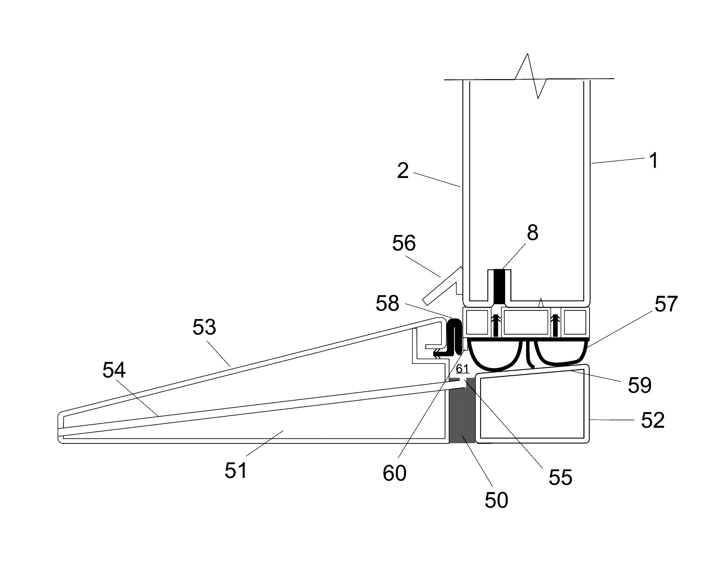
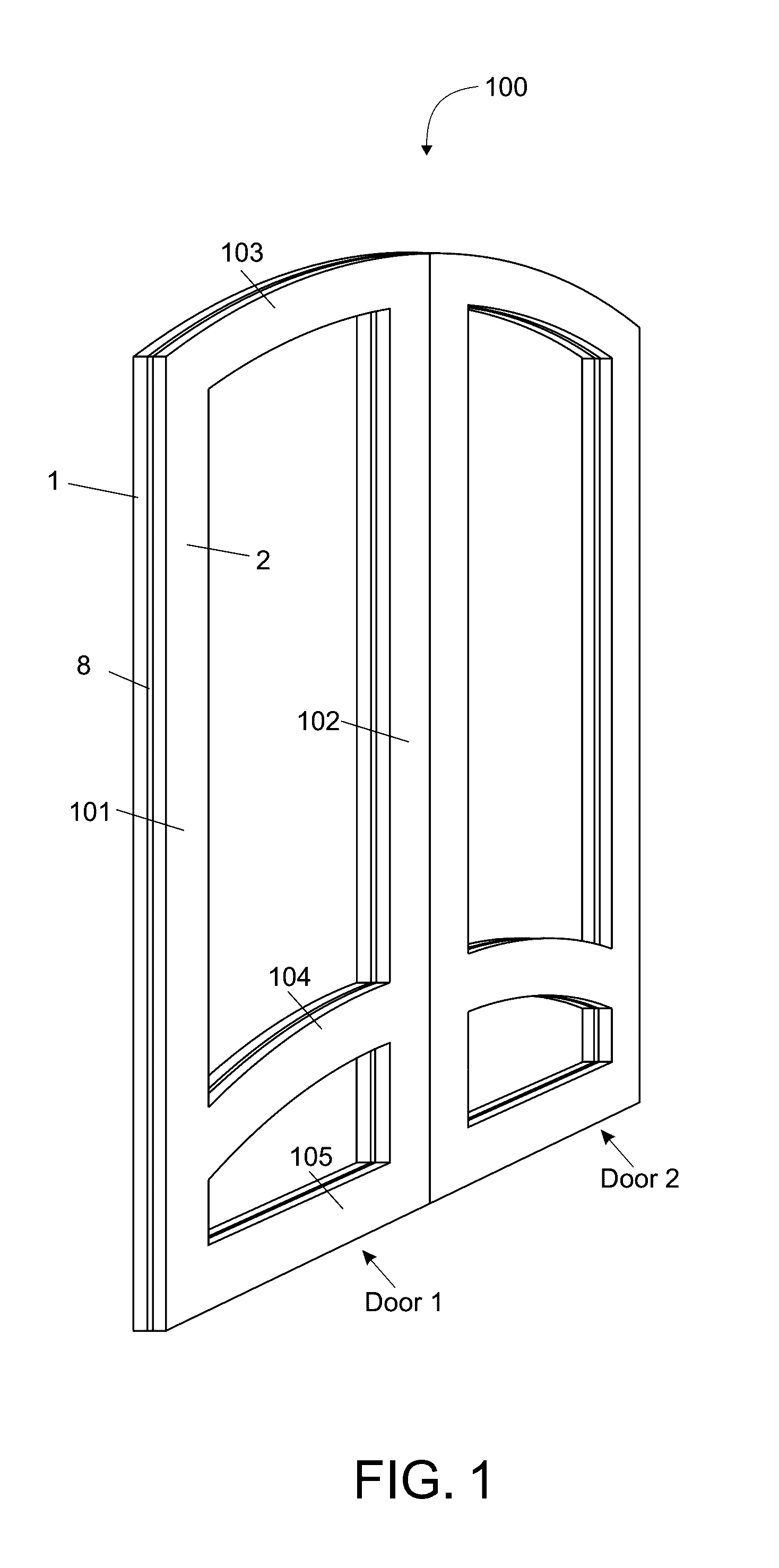
[0019]Referring now to FIGS. 1-8, a thermal break system and method for doors and windows is provided. FIG. 1 illustrates a double-insulated door 100, wherein a threshold (FIG. 6) is located below the double-insulated open doors. The double-insulated doors includes Door 1 and Door 2 each comprising a first vertical rail 101, a second vertical rail 102, a horizontal door panel 105, a curved rail 103, and a curved reinforcing plate 104. The horizontal door panel connects the first and second vertical rails at the bottom of each of the dou...


PUM

PropertyMeasurementUnit
Mechanical strengthaaaaaaaaaa
Lengthaaaaaaaaaa
Widthaaaaaaaaaa

Abstract

A door assembly providing a door frame including an inside steel panel having an inner surface and an outer surface, and a C-shaped section extending about a periphery thereof with a portion of the C-shaped section extending in part parallel to the inner surface of the inside steel panel; an outside steel panel having an inner surface and an outer surface, and a C-shaped section extending about a periphery thereof with a portion of the C-shaped section extending in part parallel to the inner surface of the outside steel panel; an insulating material interposed between respective C-shaped sections of the inside steel panel and the outside steel panel to thermally isolate the inside steel panel and the outside steel panel from each other, and said inside steel panel and outside steel panel being secured together at respective C-shaped sections to form the thermal break system.

Description

CROSS-REFERENCE TO RELATED APPLICATION[0001]The present application is a Continuation-In-Part patent application which claims priority to U.S. Utility patent application Ser. No. 14 / 833,138, filed on Aug. 23, 2015, entitled “Thermal break system and method for door and windows”, now U.S. Pat. No. 9,470,037 to issue Oct. 18, 2016, which claims priority to U.S. Provisional Patent Application Ser. No. 61 / 926,412, filed on Jan. 13, 2014, further this application claim priority to Chinese Patent Application serial number 201620628542.8, filed Jun. 23, 2016 the disclosures of which is hereby incorporated in its entirety at least by reference.FIELD OF THE INVENTION[0002]The present invention relates to the technical field of building materials, more particularly a thermal break system and method for doors and windows.BACKGROUND OF THE INVENTION[0003]Aluminum and other metals are often used for the structure of many doors and windows due to their strength and ductability, which facilitates ...

Claims


Application Information

Patent Timeline
IPC IPC(8): E06B1/22E06B1/70E06B7/14E06B7/22E06B1/52E06B1/32
CPCE06B1/22E06B1/52E06B1/70E06B7/14E06B7/22E06B1/32E05B17/0075E06B3/723E06B2003/7076E06B7/2303E06B7/2309E06B7/2316E06B7/26E06B7/2312E06B2001/707E06B1/16E06B7/16
Inventor HAYNES, ROBIN
Owner DONATELLO DOORS INC
Why Eureka
Try Eureka