Velocity stack mounted air filter assembly

a technology of air filter assembly and stack mounted air, which is applied in the direction of machines/engines, combustion-air/fuel-air treatment, and separation processes, etc., can solve the problems of engine repair and maintenance that is difficult and time-consuming, and the hermetic seal provided by the adhesives and sealants can also deteriorate and become compromised, so as to achieve more reliable and resilient structural interfaces

Inactive Publication Date: 2011-11-17
R2C PERFORMANCE PRODS
View PDF19 Cites 5 Cited by
  • Summary
  • Abstract
  • Description
  • Claims
  • Application Information

AI Technical Summary

Benefits of technology

The base tray of this invention can be installed and uninstalled in minutes with simple tools and eliminates the need to use messy and troublesome sealants to mount and seal the air box to the velocity stacks. The mounting shoes are specifically formed or molded, as well as positioned on the base tray, to accommodate the particular style or arrangement of velocity stacks on which the base tray will be mounted. The quick release latches that securely hold the filter box to the base tray allow the filter box to be removed from the base tray in seconds for cleaning or replacement. The quick release also eliminates the need for any tie-rod fasteners extending through the filter box.
The use of the pliable mounting shoes in this invention provides a more reliable and resilient structural interface for mounting the base tray to the velocity stacks. The annular collar of the pliable mounting shoes wrap physically around the velocity stacks and hose clamps securely holds the collar to the stack, which ensures a positive seal between the stacks and base tray, as well as, creating the holding force, which supports the base tray. The bowl shaped depression in the mounting shoes from which the collar diverges helps dampen and isolate the base tray from engine vibrations.

Problems solved by technology

The use of adhesive sealants to secure the mounting tray to the stacks makes engine repair and maintenance more difficult and time consuming.
The hermetic seal provided by the adhesives and sealants can also deteriorate and become compromised by engine vibrations.

Method used


Image

  • Velocity stack mounted air filter assembly
  • Velocity stack mounted air filter assembly
  • Velocity stack mounted air filter assembly

Examples


Embodiment Construction

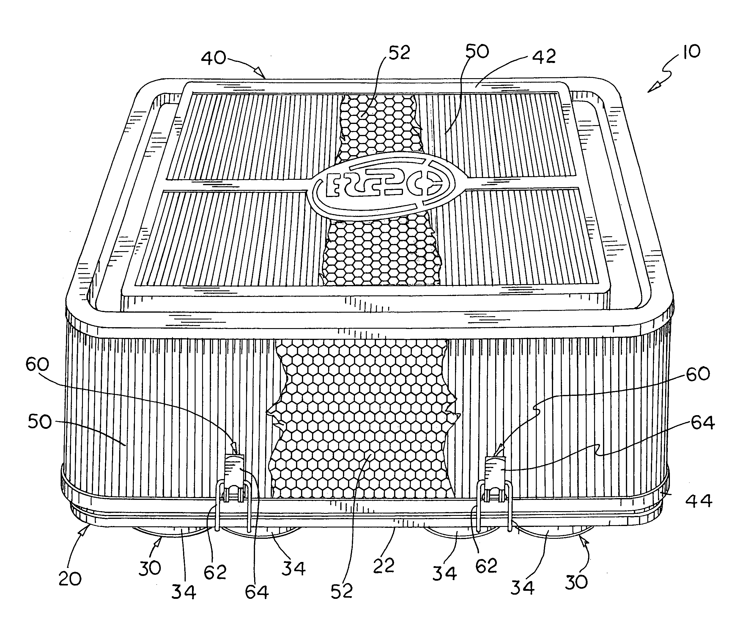
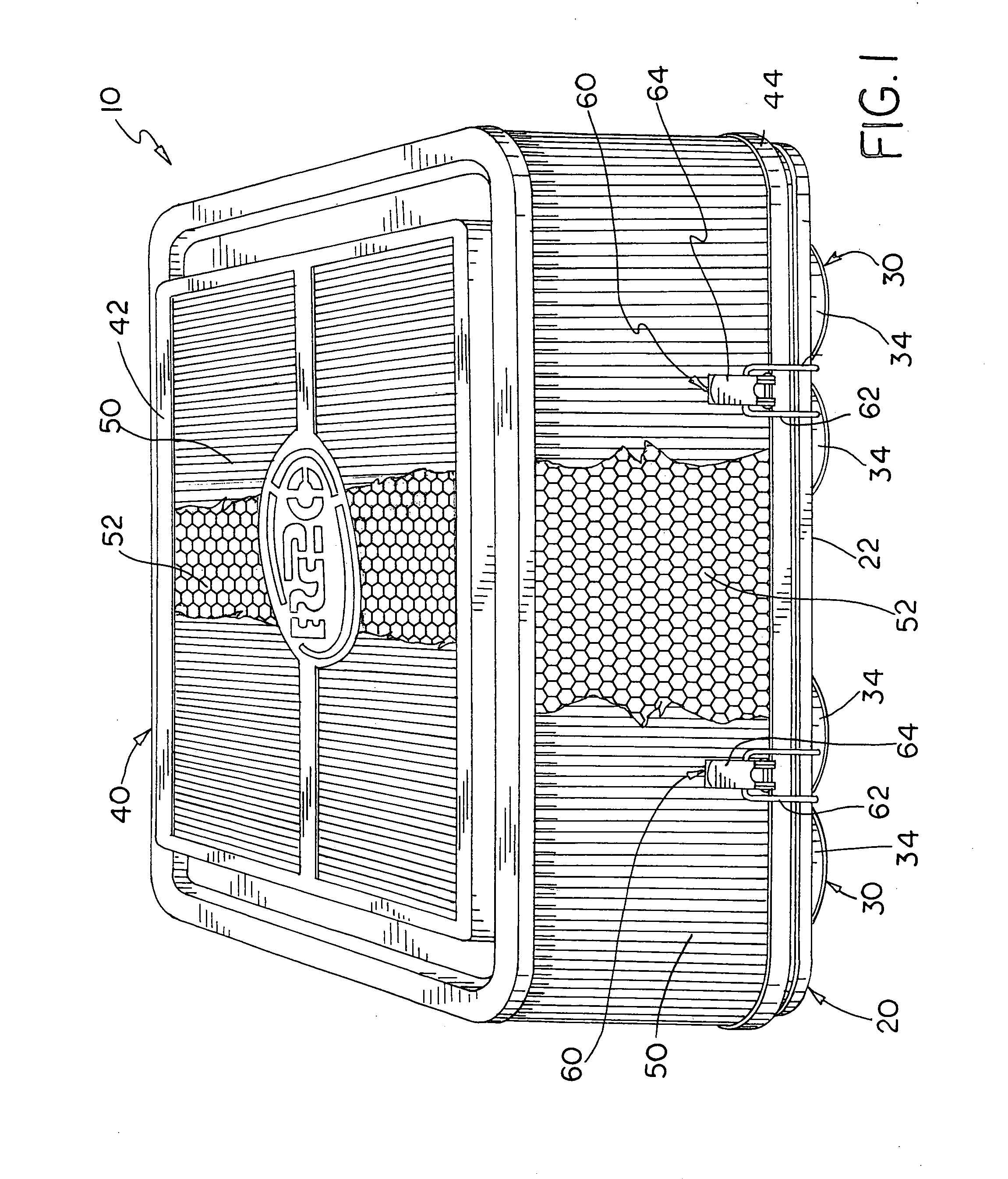
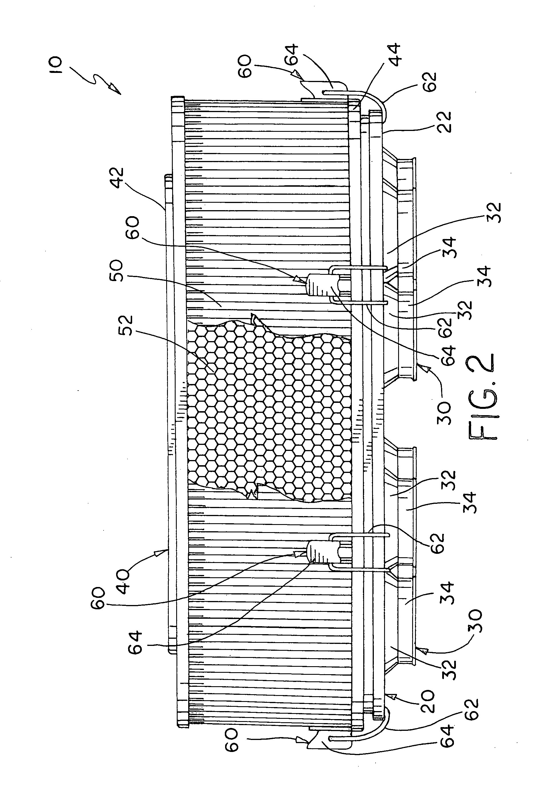
Referring now to the drawings, FIGS. 1-8 illustrate an embodiment of the air filter assembly or air box of this invention, which is designated as reference numeral 10. Air box 10 is a box-style air filter assembly designed to mount to the velocity stacks of fuel injection systems on small internal combustion engines. For simplicity of explanation, air box 10 is illustrated in the figures and describe hereafter in use with an injector system having four sets of “Siamese” style velocity stacks 4 (paired injector tubes) that extend vertically from the conventional fuel injector system 3 on a small block V8 engine 2, although the air box of this invention can be modified to accommodate any style or arrangement of velocity stacks within the teachings of this invention.

As shown, air box 10 includes a flat base tray 20 mounted to velocity stacks 4 and detachable filter box 40. Base tray 20 is constructed of carbon fiber composite, but may be constructed of other light-weight, heat resistan...


PUM

PropertyMeasurementUnit
velocityaaaaaaaaaa
volumeaaaaaaaaaa
timeaaaaaaaaaa

Abstract

The air filter assembly or “air box” includes a flat base tray mounted to velocity stacks and a detachable filter box. The base tray includes a number of pliable mounting shoes, which are seated within openings formed in the base tray. The mounting shoes are formed or molded of a pliable synthetic rubber and are configured to have a number of ports through which the velocity stacks extend. Each stack port is defined by a bowl shaped depression that diverges into an annular collar. The base tray is mounted to the velocity stacks by hose clamps that compress the annular collars of the mounting shoes around the stacks. The detachable filter box is held to the base tray by six quick release latches.

Description

This invention relates to an air filter assembly for combustion engines, and in particular a box-style air filter assembly mountable to the vertical velocity stacks of a fuel injection system on the combustion engines of a vehicle.BACKGROUND OF THE INVENTIONBox-style air filter assemblies or “air boxes” are commonly used on sprint car engines and other types of performance engines that use fuel injection systems that have multiple vertical “velocity stacks” or “injector tubes.” Box-style air boxes are mounted directly to the vertical velocity stacks of fuel injection systems and provide a large volume plenum enclosure that services all the stacks replacing smaller individual filters mounted to each stack.A conventional air box includes a flat mounting tray which is secured to the velocity stacks and a detachable filter box. Heretofore, holes were manually cut in the flat mounting tray to accept the velocity stacks therethrough. The mounting tray is secured to the stacks by an adhesi...

Claims


Application Information

Patent Timeline
Patent Type & Authority Applications(United States)
IPC IPC(8): B01D50/00B01D46/00
CPCB01D46/2403B01D2275/205F02M35/02491F02M35/0203F02M35/0245B01D2279/60
Inventor TROXELL, RONALD C.DESAI, ROBIN R.
Owner R2C PERFORMANCE PRODS
Why Eureka
Try Eureka