Valve door having a force directing component and retractable instruments comprising same

a technology of force directing and valve doors, which is applied in the field of retractable writing instruments having valve doors with force directing components, can solve the problems that the prior art design is not particularly well suited to relatively large writing tips, and achieve the effect of reducing lid deflection and reducing ink evaporation

Active Publication Date: 2012-07-24
SANFORD LP
View PDF368 Cites 1 Cited by
  • Summary
  • Abstract
  • Description
  • Claims
  • Application Information

AI Technical Summary

Benefits of technology

[0005]A valve door for a retractable marker comprises a lid having first and second surfaces and a connecting means for connecting the lid with an actuating mechanism, the connecting means being adapted to distribute forces from the actuating mechanism across a portion of the first lid surface in order to bias the lid to a closed position. A force directing member is attached to the first lid surface, the force directing member being adapted to distribute force from the connecting means over a portion of the lid surface, thereby maintaining a positive seal and reducing lid deflection.
[0007]A retractable writing instrument comprises a writing member having a nib, the writing member being disposed in a writing instrument body. A seal cylinder is disposed within the writing instrument body, the seal cylinder surrounding a portion of the writing member including the nib, and having an open end. A lid selectively seals or exposes the open end of the seal cylinder. A moving mechanism is disposed between the writing instrument body and the writing member, the moving mechanism moving the writing member between a retracted position in which the nib is disposed within the seal cylinder and an extended position in which the nib protrudes outside of the seal cylinder through the open end of the seal cylinder. A connecting means connects the lid to the moving mechanism, the connecting means applies force generated by the moving mechanism across at least a portion of one side of the lid, thereby biasing the lid to a closed position in which the lid seals the open end of the seal cylinder. The lid includes a pair of ribs positioned between the lid and the connecting means, the ribs elevating a portion of the connecting means above a portion of a lid surface distal to the seal cylinder, the pair of ribs applying force from the connecting means across a portion of the lid surface distal to the seal cylinder, thus reducing lid deflection when the lid is in the closed position and thereby reducing ink evaporation.

Problems solved by technology

However, the prior art design is not especially well suited for relatively large writing tips, for example, those used to produce markers intended to convey information to groups of people such as dry erase markers, and other similarly sized markers, as the seal cover does not adequately seal large diameter openings.

Method used


Image

  • Valve door having a force directing component and retractable instruments comprising same
  • Valve door having a force directing component and retractable instruments comprising same
  • Valve door having a force directing component and retractable instruments comprising same

Examples


second embodiment

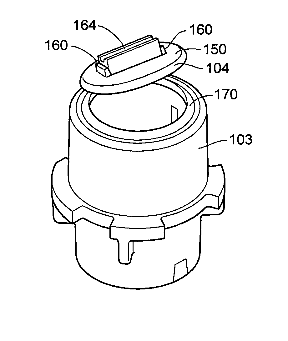
[0030]A second alternate embodiment of a lid 204 constructed and arranged in accordance with teachings of the disclosure is shown in FIG. 7. In the second embodiment, the force directing means takes the form of a block 260. The connecting means 215 extends across the first surface 250 of the lid 204 and across the block 260. Thus, the block 260 elevates the connecting means 215 above the first surface 250 of the lid 204 and directs the force from the connecting means 214 through the lid 204 and substantially inside the diameter of the valve seal ring 170 (FIG. 6B). The block 260 may optionally include a groove, channel, or similar retention features(s) (not shown) to help retain the connecting means 215 therein. As in other embodiments, the force directing component 260 elevates the connecting means above a least a portion of the first surface 250, and the connecting means 215 is disposed transversely to a hinge 228 for opening / closing the valve assembly (not shown). The block 260 m...

third embodiment

[0031]A third alternate embodiment of a lid 304 is shown in FIG. 8. In the third embodiment, a bridge 380 is provided between the two ribs 360 on the first lid surface 350. The bridge 380 may optionally include a retention feature such as a groove or channel 382 for positioning and stabilizing the connecting means 315 across lid surface 350, thereby maintaining the connecting means 315 in a desired orientation across the lid 304.

[0032]In yet another embodiment, the force director could be provided as a single elevated structure positioned substantially in the center of the lid, thereby forming a tower. The tower centrally distributes the forces from the connecting member across the top of the lid, and substantially inside the diameter of the seal.

[0033]In still another embodiment, the force directing member could be attached to the connecting member as opposed to being attached to the lid. When the connecting member is positioned on the top of the lid such that the force directing m...


PUM


Abstract

A valve door for a seal cylinder comprises a lid having first and second surfaces and a connecting means connecting the lid with an actuating mechanism, the connecting means distributes forces from the actuating mechanism across a portion of the first lid surface in order to bias the lid to a closed position. A force directing member is attached to the first lid surface, the force directing member being adapted to distribute force from the connecting means over a portion of the lid surface, thereby maintaining a positive seal and reducing lid deflection.

Description

BACKGROUND[0001]1. Field of the Disclosure[0002]The disclosure relates generally to retractable instruments and more specifically to cap-less, retractable writing instruments having a valve door with a force directing component.[0003]2. Related Technology[0004]One example of a cap-less, retractable writing instrument is shown in U.S. Pat. No. 5,048,990, which is hereby incorporated by reference. The cap-less writing instrument includes a writing member having a writing tip. The writing member is accommodated in a seal cylinder that is disposed inside a writing instrument body. A seal cover for closing an end opening of the seal cylinder is disposed on the seal cylinder near the front end of the seal cylinder. A writing member moving mechanism moves the writing member forwardly and locks the writing member at a writing position with the writing tip protruding through the front of the writing instrument body. The moving mechanism includes a thread-like member that connects the writing...

Claims


Application Information

Patent Timeline
Patent Type & Authority Patents(United States)
IPC IPC(8): B43K5/17
CPCA45D34/041A45D40/20A45D40/261B43K8/028A45D2034/002A45D2040/201A45D2200/051A45D2200/055A45D2040/0006
Inventor RENNECKER, DANIELVANDERHOOF, RUSS
Owner SANFORD LP
Why Eureka
Try Eureka