Optical Imaging Assembly

a technology of optical imaging and assembly, applied in the field of optical imaging modules, can solve the problems of difficult to maintain a high yield of lens modules, conventional structures are no longer capable of accomplishing missions, etc., and achieve the effect of high image quality of optical imaging modules and good defocus sta

Inactive Publication Date: 2017-02-09
VISTA OPTRONICS
View PDF1 Cites 0 Cited by
  • Summary
  • Abstract
  • Description
  • Claims
  • Application Information

AI Technical Summary

Benefits of technology

[0008]The present invention provides a five-element optical imaging module. With controlling the refractive power and key relationship

Problems solved by technology

But now the conventional structure was no longer capable to accomplish the mission, since the aberrations and the total track length of the optical system thereby cannot be further modified while achieving a high resolution or a

Method used


Image

  • Optical Imaging Assembly
  • Optical Imaging Assembly
  • Optical Imaging Assembly

Examples


first embodiment

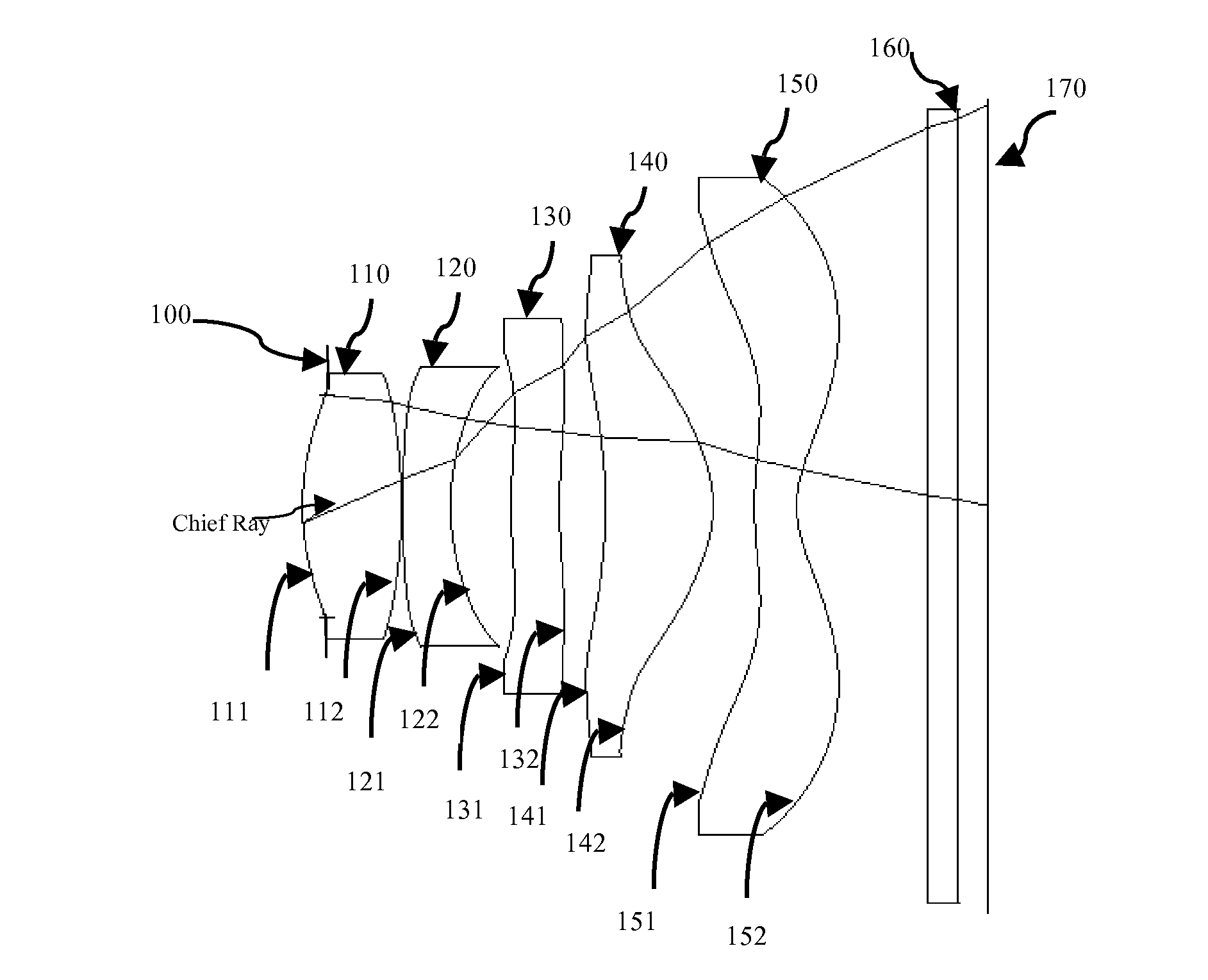
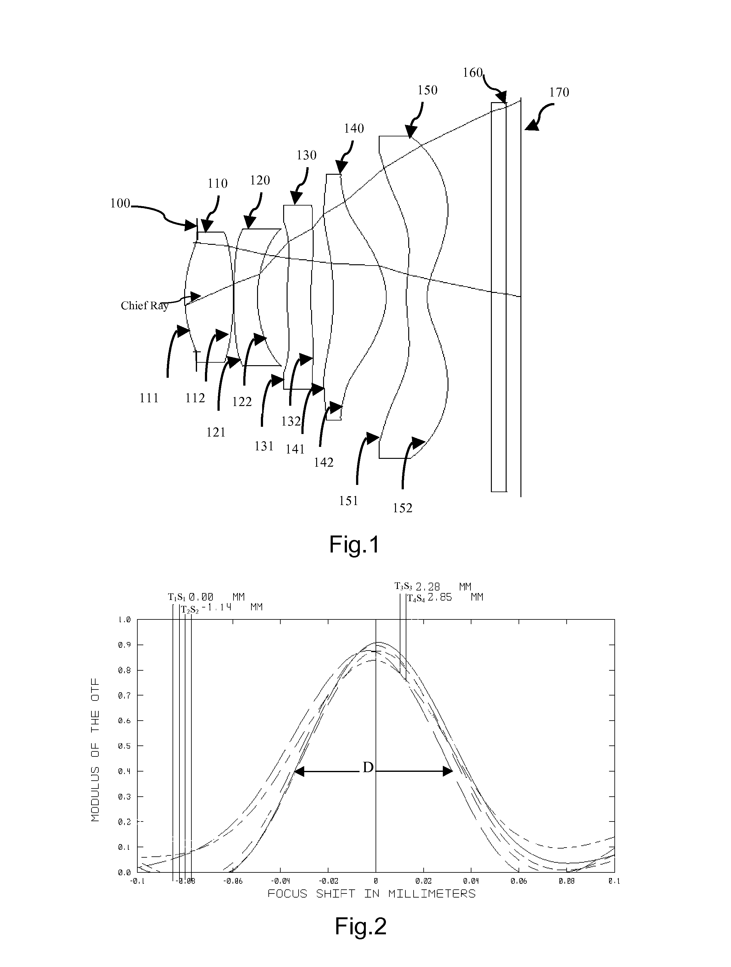
[0039]Referring to FIG. 1 to 1C for the present invention, the optical imaging module, sequentially arranged from an object side to an image side along an optical axis, comprises an aperture stop 100, a first lens element 110, a second lens element 120, a third lens element 130, a fourth lens element 140, a fifth lens element 150, an IR-cut filter 160 and an image plane 170, wherein all the lens elements 110, 120, 130,140 and 150 are made of plastic.

[0040]The first lens element 110 with positive refractive power has a convex object side surface 111 and a convex image side surface 112.

[0041]The second lens element 120 with negative refractive power has an object side surface 121 being convex in a peripheral region and a concave image-side surface 122, and the object-side surface 121 is thereof being aspheric.

[0042]The third lens element 130 with negative refractive power has an object side surface 131 being concave in a peripheral region and both the object-side surface 131 and the i...

second embodiment

[0048]With reference to FIG. 4 the optical imaging module in second embodiment of the present invention, sequentially arranged from an object side to an image side along an optical axis, comprises an aperture stop 200, a first lens element 210, a second lens element 220, a third lens element 230, a fourth lens element 240, a fifth lens element 250, an IR-cut filter 260 and an image plane 270, wherein all the lens elements 210, 220, 230,240 and 250 are made of plastic.

[0049]The first lens element 210 with positive refractive power has an object side surface 211 being convex in a paraxial region and a convex image side surface 212.

[0050]The second lens element 220 with negative refractive power has an object side surface 221 being convex in a peripheral region and a concave image-side surface 222, and the object-side surface 221 is thereof being aspheric.

[0051]The third lens element 230 with negative refractive power has an object side surface 231 being concave in a peripheral region ...

third embodiment

[0056]Referring to FIG. 7 for the present invention, the optical imaging module sequentially arranged from an object side to an image side along an optical axis, comprises an aperture stop 300, a first lens element 310, a second lens element 320, a third lens element 330, a fourth lens element 340, a fifth lens element 350, an IR-cut filter 360 and an image plane 370, wherein all the lens elements 310, 320, 330,340 and 350 are made of plastic.

[0057]The first lens element 310 with positive refractive power has a convex object side surface 311 and a convex image side surface 312.

[0058]The second lens element 320 with negative refractive power has a concave image-side surface 322, and the object-side surface 321 is thereof being aspheric.

[0059]The third lens element 330 with positive refractive power has an object side surface 331 being concave in a peripheral region and both the object-side surface 331 and the image-side surface 332 are aspheric.

[0060]The fourth lens element 340 with ...


PUM


Abstract

An optical imaging module used in portable devices is described. In order from an object side to an image side, the module comprises an aperture stop, a first lens element with positive refractive power having a convex object-side surface and a convex image-side surface; a second lens element with negative refractive power having a concave image-side surface and a object-side surface being convex in a peripheral region; a third lens element with refractive power; a fourth lens element with refractive power having a convex image-side surface; a fifth lens element with positive refractive power having an image-side surface being concave in a paraxial region and convex in a peripheral region; and wherein the optical imaging module used in the portable devices satisfies: 0.052 mm≦D≦0.082 mm, where D represents a maximum effective focus shifts range under all the defocus curves at 0.4 modulus of the OTF (optical transfer function).

Description

BACKGROUND OF THE INVENTION[0001]1. Field of the Invention[0002]The present invention relates to an optical imaging module and more particularly to an optical imaging module used in portable devices.[0003]2. Description of the Prior Art[0004]In recent years, the development of the optical lens module in digital cameras, web cameras and portable phone cameras becomes more rapid with the sharp increase in demand of people for high image capturing quality. High resolution, large field of view for sub camera, smaller size and etc are all considered more and more by consumers.[0005]Generally, for the sake of meeting customers' demands, especially demands for high imaging resolution a conventional lens module is used to be a three-lens structure or a four-lens structure. But now the conventional structure was no longer capable to accomplish the mission, since the aberrations and the total track length of the optical system thereby cannot be further modified while achieving a high resoluti...

Claims


Application Information

Patent Timeline
IPC IPC(8): G02B13/00G02B27/00G02B5/20G02B9/60
CPCG02B13/0045G02B5/208G02B27/0025G02B9/60
Inventor SUN, FENGQING
Owner VISTA OPTRONICS
Why Eureka
Try Eureka