Optical operating input detection apparatus, automatic vending machine, and optical operating input detection method

an optical operating input and detection apparatus technology, applied in the direction of instruments, computing, electric digital data processing, etc., can solve the problem of not being able to find the free touch panel of the known

Active Publication Date: 2017-02-09
FUJI ELECTRIC CO LTD
View PDF4 Cites 5 Cited by
  • Summary
  • Abstract
  • Description
  • Claims
  • Application Information

AI Technical Summary

Benefits of technology

[0010]In view of the foregoing, it is desirable to provide an optical operating input detection apparatus, an automatic vending machine, and an optical operating input detection method capable of inhibiting an occurrence of false operations on the touch panel.

Problems solved by technology

As a result, the known touch panels are not free from false operations involved in the operating unit erroneously touching the touch panel screen during selection of a specific position by the operating unit.

Method used


Image

  • Optical operating input detection apparatus, automatic vending machine, and optical operating input detection method
  • Optical operating input detection apparatus, automatic vending machine, and optical operating input detection method
  • Optical operating input detection apparatus, automatic vending machine, and optical operating input detection method

Examples


Embodiment Construction

[0039]The following describes modes for carrying out the invention with reference to the accompanying drawings.

[0040]Overview of Optical Operating Input Detection Apparatus

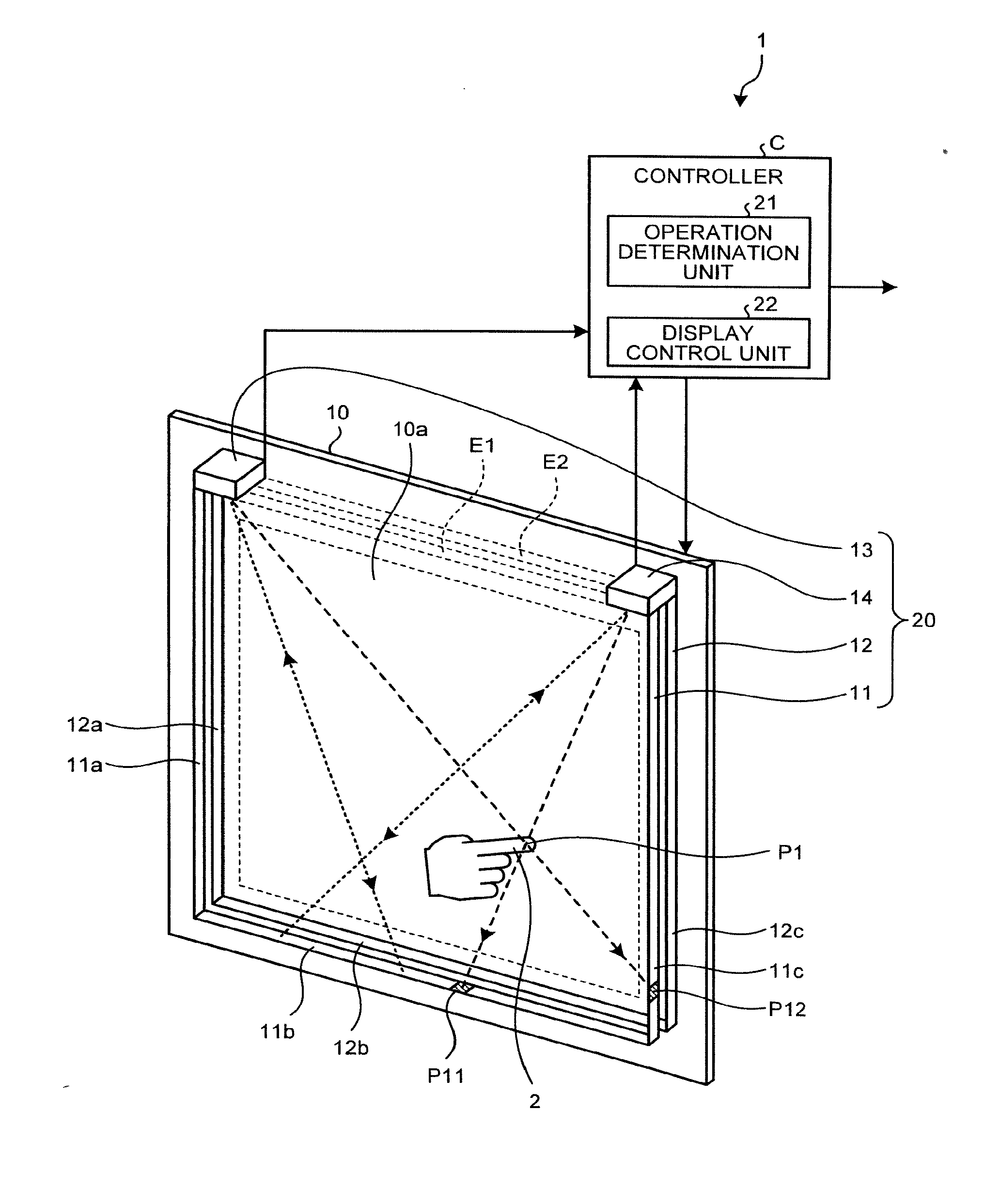
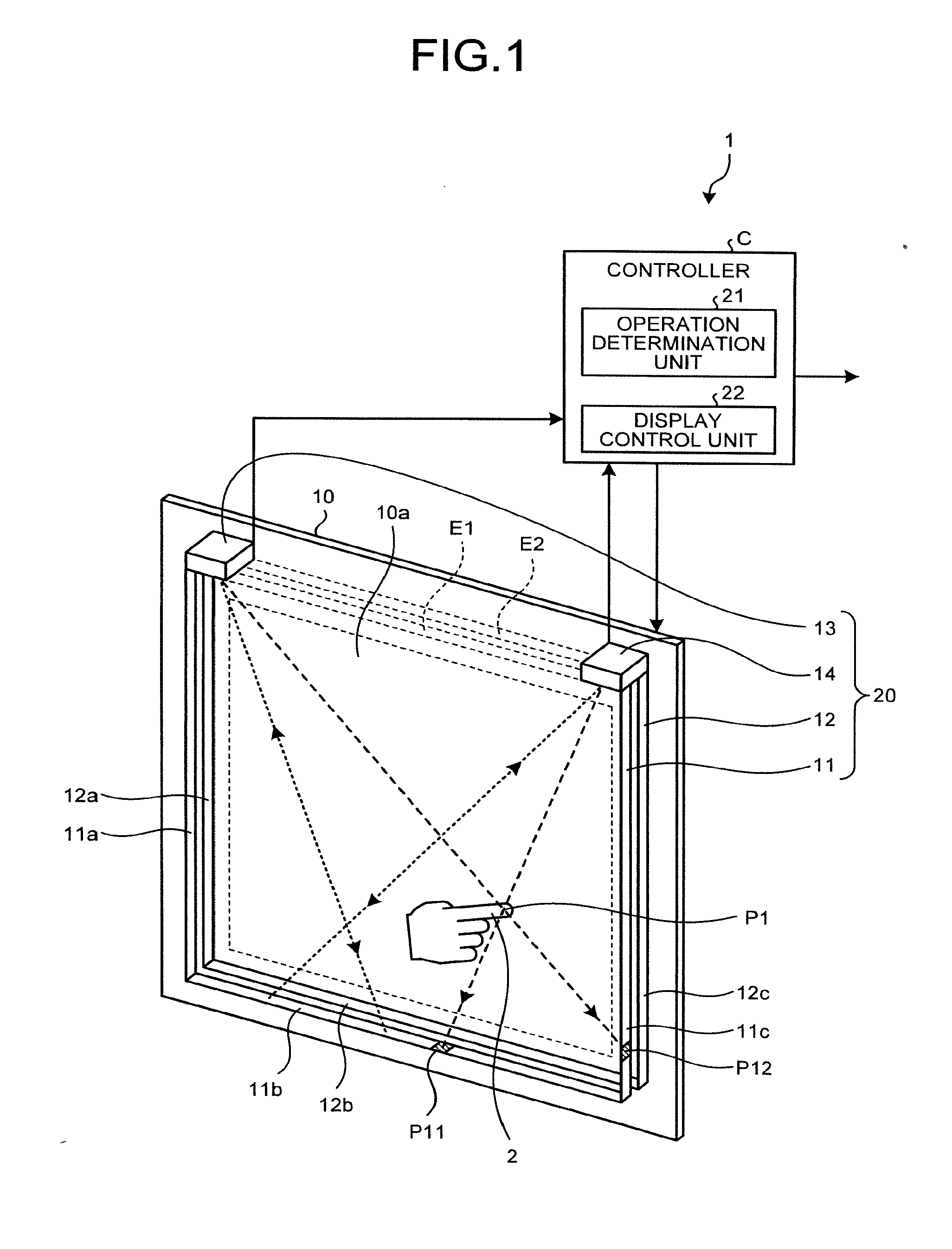
[0041]FIG. 1 is a schematic diagram illustrating a configuration of an optical operating input detection apparatus 1 according to the present disclosure. FIG. 2 is a plan view illustrating a detection unit 20 of the optical operating input detection apparatus 1 illustrated in FIG. 1. As illustrated in FIG. 1, the detection unit 20 is disposed on a surface of a display panel 10 having a display area surface 10a and functions as an optical touch panel.

[0042]The detection unit 20 includes a rectangular first detection layer E1 and a rectangular second detection layer E2. More specifically, the first detection layer E1 extends in parallel with, and is spaced a predetermined distance away from, the display area surface 10a on the display panel 10 and has a surface area including the display area surface 10a. The second...


PUM


Abstract

An optical operating input detection apparatus includes: a detection unit configured to optically detect an operating input by the operating unit on respective first and second detection layers, the first detection layer extending in parallel with a display area surface on the display panel to be spaced a predetermined distance away from the display area surface and having a surface area including the display area surface, the second detection layer being disposed between the display area surface and the first detection layer and having a surface area identical to the surface area of the first detection layer; and an operation determination unit configured to determine operating detail of the operating unit based on a detected image on the respective first and second detection layers.

Description

CROSS-REFERENCE TO RELATED APPLICATIONS[0001]This application is a continuation of PCT International Application No. PCT / JP2015 / 063850 filed on May 14, 2015 which designates the United States, incorporated herein by reference, and which claims the benefit of priority from Japanese Patent Application No. 2014-111765 filed on May 29, 2014 and Japanese Patent Application No. 2014-230951 filed on Nov. 13, 2014, incorporated herein by reference.BACKGROUND[0002]1. Technical Field[0003]The disclosure relates to an optical operating input detection apparatus, an automatic vending machine, and an optical operating input detection method.[0004]2. Related Art[0005]A late automatic vending machine model includes a display that is incorporated in a front door thereof and that displays commodity samples as an image and, for example, a touch panel that allows a specific commodity to be selected (see Japanese Patent Application Laid-open No. 11-232537). The use of the display and the touch panel ca...

Claims


Application Information

Patent Timeline
Patent Type & Authority Applications(United States)
IPC IPC(8): G06F3/042G07F9/00
CPCG07F9/00G06F3/042G06F3/0421G06F2203/04108G07F9/0235
Inventor MAEKAWA, TOMONORIKOBAYASHI, SHINICHI
Owner FUJI ELECTRIC CO LTD
Why Eureka
Try Eureka