Swing type working vehicle

a working vehicle and swing technology, applied in the direction of mechanical control devices, process and machine control, instruments, etc., to achieve the effect of preventing inadvertent pedal operation, reducing the number of components, and preventing false switch operation

Inactive Publication Date: 2011-02-15
YANMAR POWER TECHNOLOGY CO LTD
View PDF10 Cites 2 Cited by
  • Summary
  • Abstract
  • Description
  • Claims
  • Application Information

AI Technical Summary

Benefits of technology

[0011]In the swing type working vehicle, since base parts of the pedals are supported so as to be swung forward and backward, where when the pedals are swung backward, the pedals are brought into contact with an operating member of the hydraulic actuators to disable the operation and when swung forward, the pedals are held in a state of being brought into contact with the step in the swing type working vehicle in which a step is arranged on a front part of a swing table frame and pedals for operating hydraulic actuators are disposed on the step, the pedals can be swung and accommodated at the front part of the step when the pedals are not necessary, wherein the space for the foot portion of the operation can be enlarged. Since the operation of the hydraulic actuator cannot be performed when the pedals are swung forward, a cover for disabling the operation of the pedals becomes unnecessary, and the number of components can be reduced. The inadvertent operation of the pedals is thus reliably prevented.
[0012]In the swing type working vehicle of the present invention, since the pedal is configured to an L-shape in side view and has one side pivotally supported and the other side formed with foot placing parts on both upper and lower surfaces, the back surface serves as a foot placement when the pedals are swung forward, and a foot resting area for the operator can be ensured.
[0013]In the swing type working vehicle, since an option switch is arranged below the pedals when the pedals are swung forward, and is configured to cover the switch when the pedals are swung forward, the pedals are accommodated when the option working vehicle is not used to cover the switch exposed on the step, thereby preventing false operation of the switch.

Problems solved by technology

In the swing type working vehicle of the prior art, the operation pedal and the cover thereof occupy a certain space on the step even if operation of the operation pedal is unnecessary, and thus become a hindrance when ensuring the foot space.

Method used


Image

  • Swing type working vehicle
  • Swing type working vehicle
  • Swing type working vehicle

Examples


Embodiment Construction

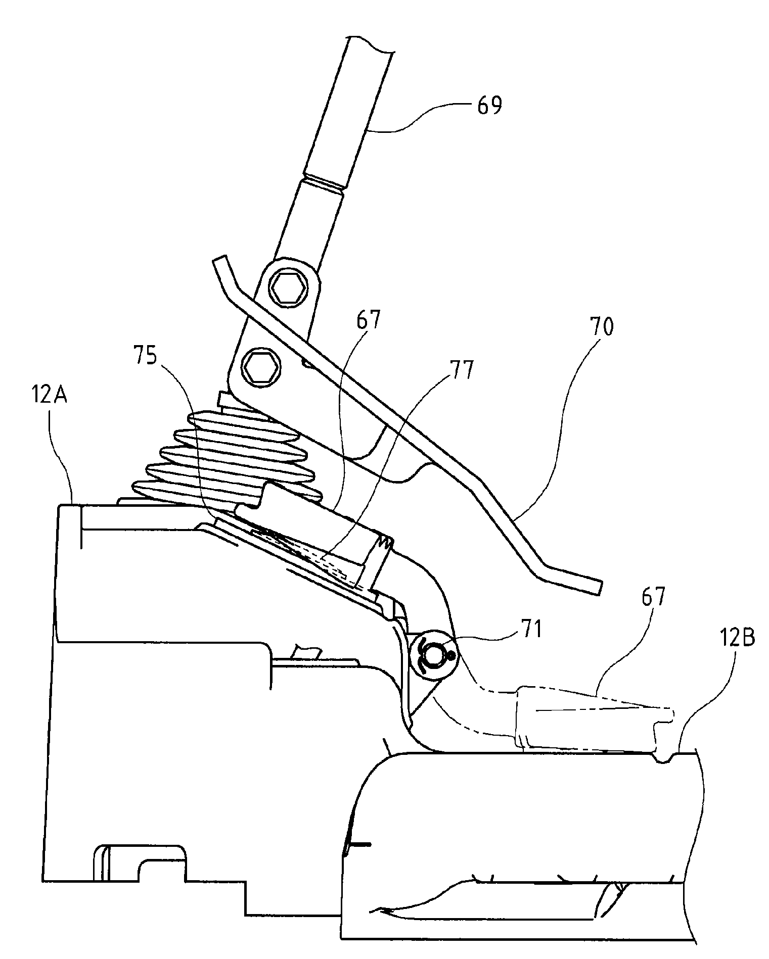
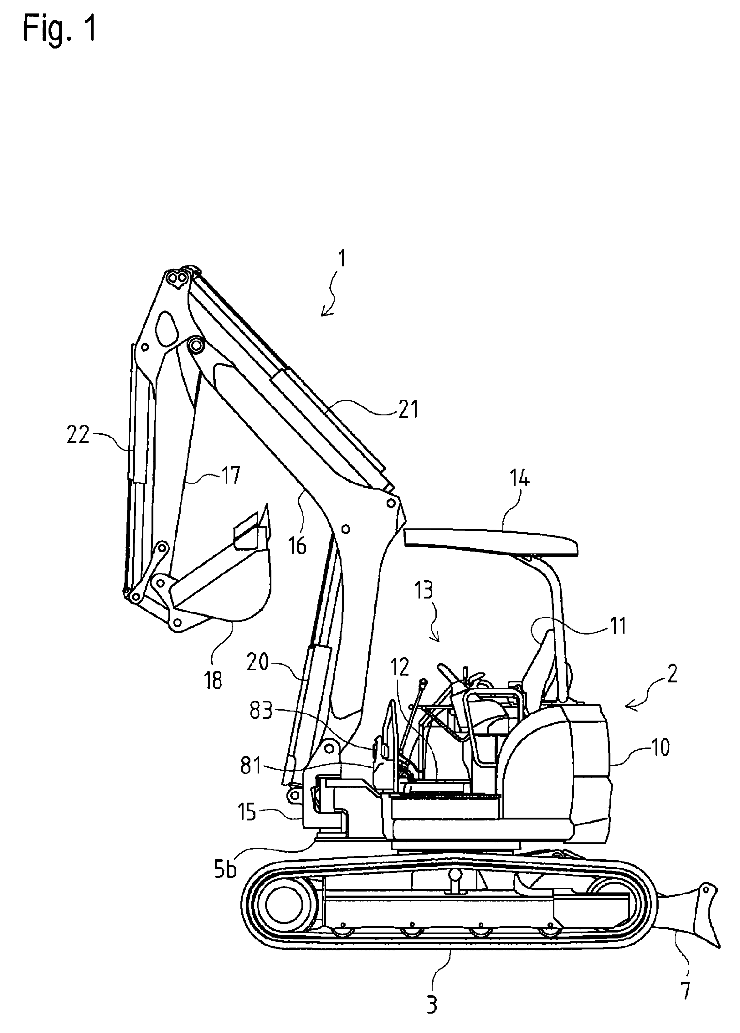
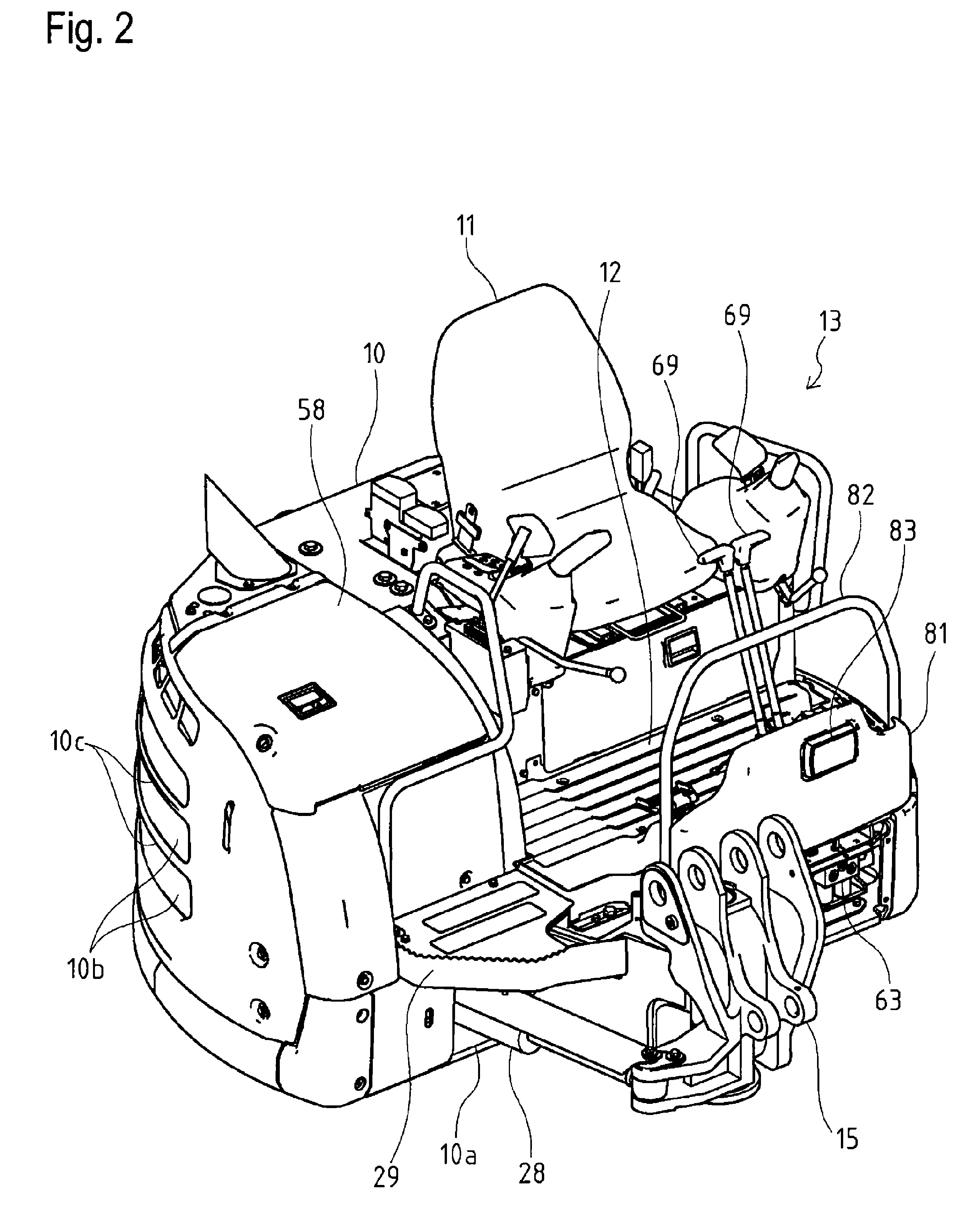
[0040]As shown in FIG. 1, FIG. 2, and FIG. 3, in a rear ultraminiature swing type power shovel in which a swing type working vehicle such as working vehicle 1 is attached at the middle in the left and right direction of the front part of a main equipment 2, a swing table frame 5 is supported in a left and right rotatable manner by way of a rotary base bearing at the middle of the upper part of a crawler traveling device 3, and a rotary motor 6 is arranged on the swing table frame 5. A blade 7 is arranged in a freely up and down turning manner on either the front or the rear side of the crawler traveling device 3. A bonnet 10 for covering an engine 8 etc. is arranged on the upper part of the swing table frame 5, and a driver's seat 11 is arranged on the bonnet 10 or on the front side of the bonnet 10. An operation lever, a lock lever, and the like are arranged near the driver's seat 11, and a travel lever and a pedal are arranged on a step 12 on the front side of the driver's seat 11...


PUM


Abstract

A swing type working vehicle, wherein a space at the foot portion of an operator can be increased when pedal operation is not required. A step is installed on the front part of a swing table frame, and pedals for operating hydraulic actuators are disposed on the step. The base parts of the pedals are supported so that these pedals can be swung forward and backward. When the pedals are swung backward, they are brought into contact with the operating members of the hydraulic actuators to disable the operation, and when the pedals are swung forward, they are held in the state of being brought into contact with the step.

Description

BACKGROUND OF THE INVENTION[0001]1. Field of the Invention[0002]The present invention relates to a structure of a swing type working vehicle including a step on a front part of a swing table frame and arranging an operation pedal for hydraulic actuator operation on the step.[0003]2. Background Art[0004]Conventionally, in a swing type working vehicle such as a power shovel, a swing table frame is generally arranged on a traveling device, a working vehicle including a boom, an arm, and an attachment such as a bucket is attached to the front part of the swing table frame, and an engine, a counter weight, and the like are arranged on the rear part of the swing table frame. A step is arranged at the front part of a drive operation unit on the swing table frame, and a boom swing operation pedal, a PTO operation pedal, and the like are arranged on the step. The pedals include a cover at the vicinity thereof, and are made non-operable by being covered by such cover (see e.g., Patent Documen...

Claims


Application Information

Patent Timeline
Patent Type & Authority Patents(United States)
IPC IPC(8): G05G1/30E02F9/16G05G1/48G05G1/58
CPCE02F3/301E02F3/307E02F9/0866G05G1/30G05G1/58E02F9/2004Y10T74/20888E02F9/16B66C13/56
Inventor TANAKA, KATASHI
Owner YANMAR POWER TECHNOLOGY CO LTD
Why Eureka
Try Eureka