
Planning a flight path by identifying key frames

a key frame and flight path technology, applied in the field of flight path planning by key frame, can solve the problems of difficult navigation skills for an average pilot, common vehicle crash, and difficulty in controlling a drone aircraft vehicl

Active Publication Date: 2017-02-09
FUZHOU LIGHTFLOW TECH CO LTD
View PDF2 Cites 78 Cited by
  • Summary
  • Abstract
  • Description
  • Claims
  • Application Information

AI Technical Summary

Benefits of technology

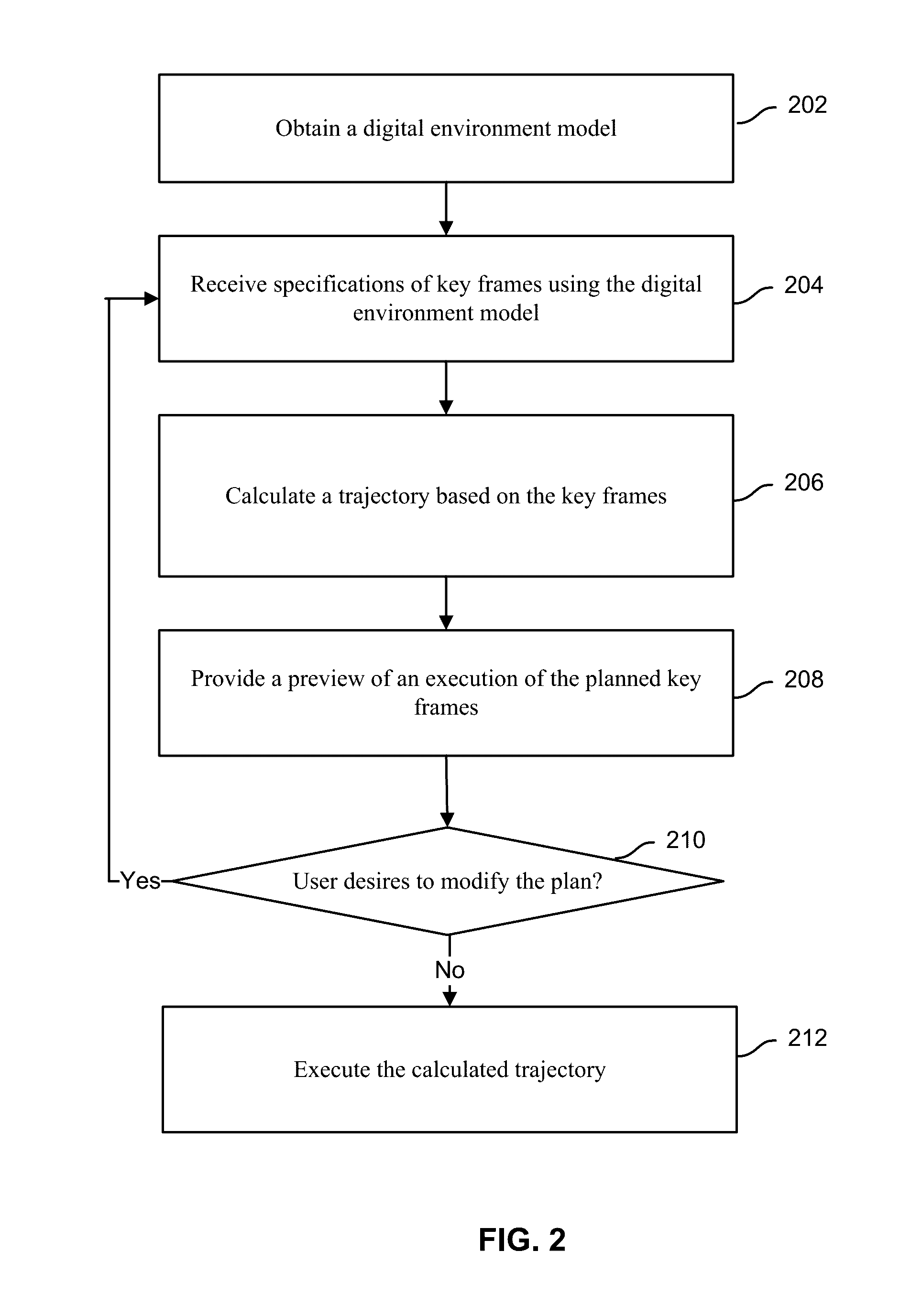
The invention is a system and method for planning and controlling the operation of a drone aircraft vehicle. It aims to improve the accuracy and safety of drone flights by automating the process of planning and executing a flight path. The invention allows for the specification of a plurality of key locations within a virtual environment and the final planned path is physically executed later using the vehicle. The trajectory between the key locations is calculated and a three-dimensional virtual preview of the trajectory is provided for confirmation and adjustment by the user. The invention can be implemented in various ways, including as a process, apparatus, system, composition of matter, computer program product, and processor. Overall, the invention improves the efficiency and safety of drone flights by automating the planning and control process.

Problems solved by technology

Controlling a drone aircraft vehicle takes a considerable amount of skill.
Unfortunately, vehicle crashes are common due to pilot error.
Not only are these traditional controllers not intuitive for a novice pilot, timing precise movements requires quick reaction time and navigation skills that are often very difficult for an average pilot.
As additional time critical tasks are required of the pilot, it becomes even more difficult for a pilot to effectively control the vehicle and its camera parameters during flight to achieve a desired result.
However, because the actions of the operators are dependent on each other, communication problems between the operators may lead to difficulty in achieving the desired result.

Method used


Image

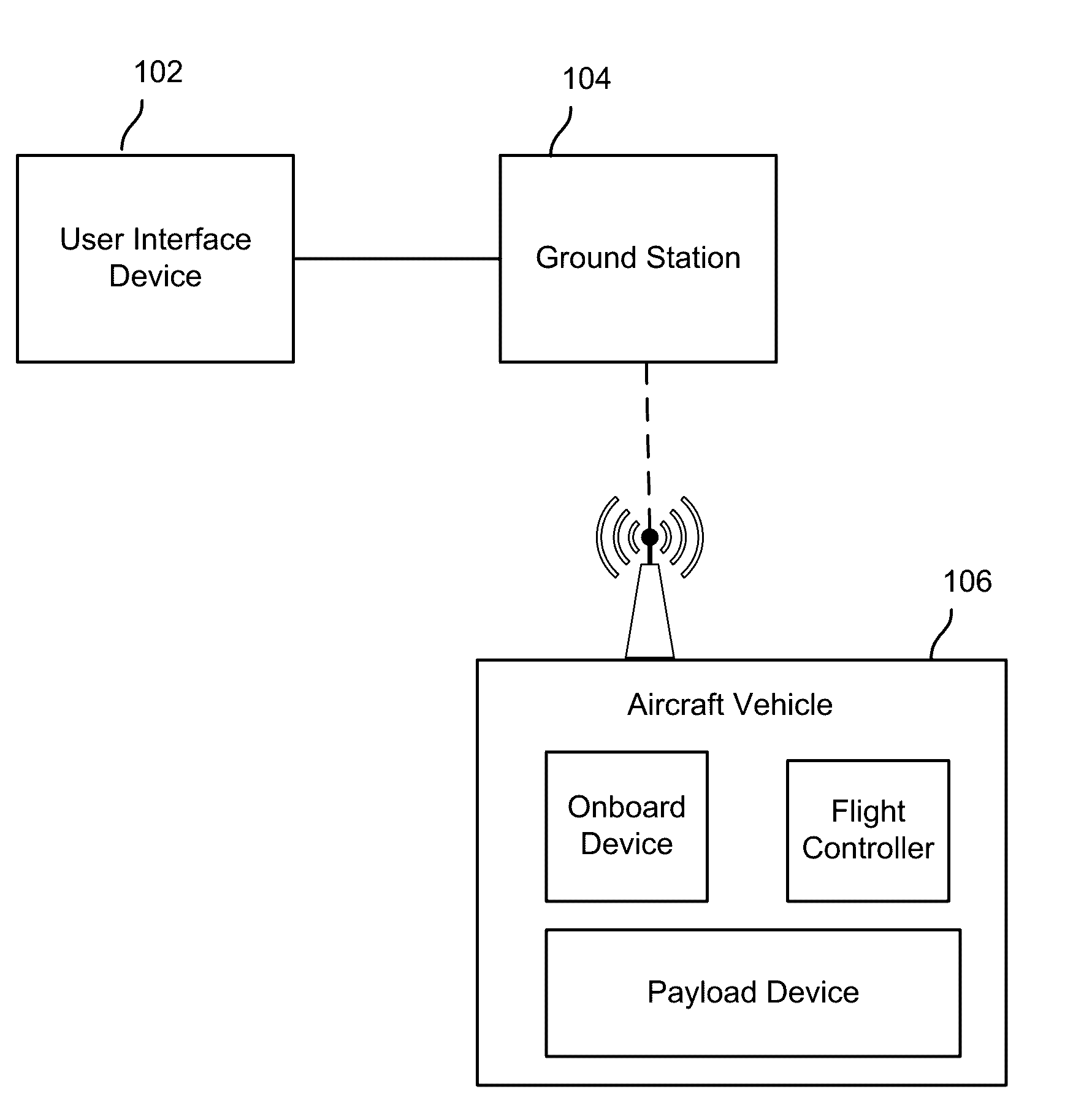
  • Planning a flight path by identifying key frames
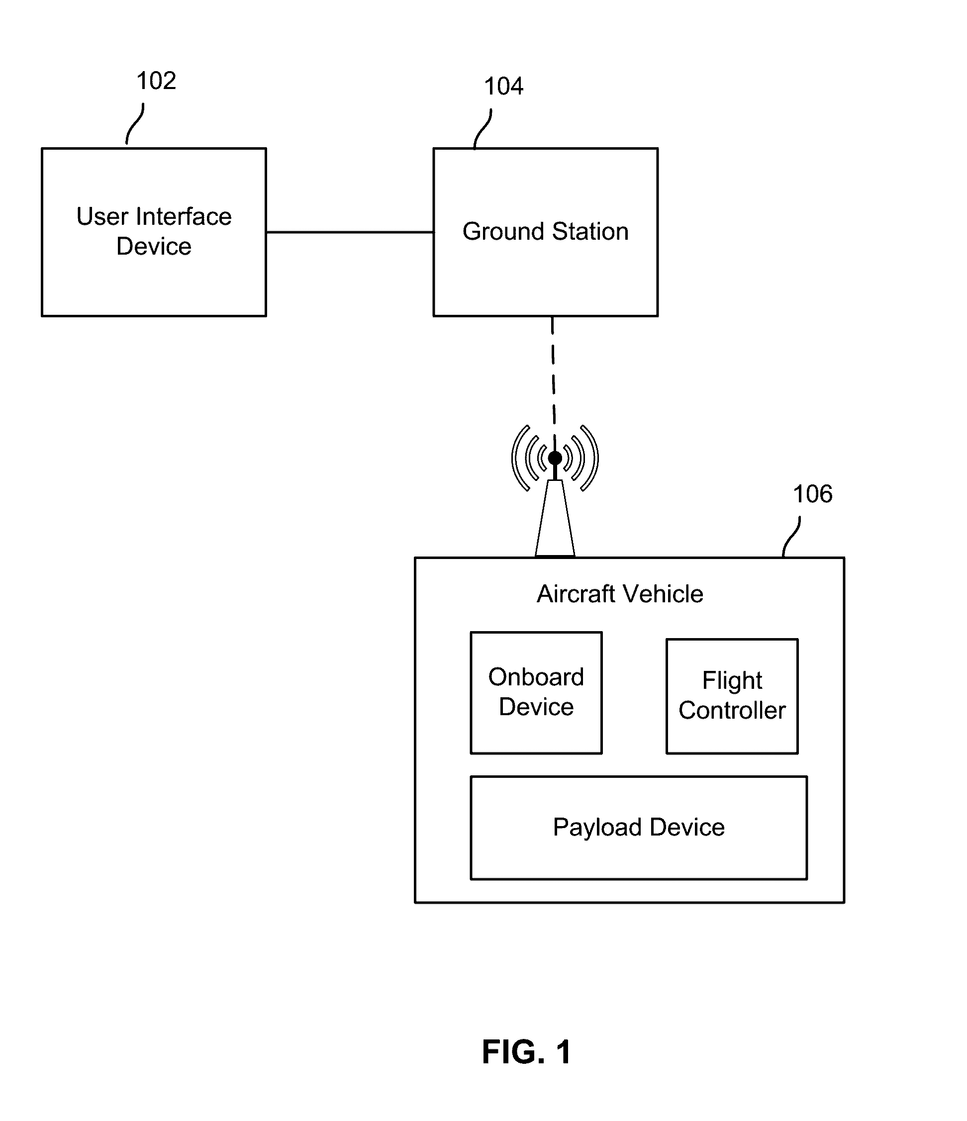
  • Planning a flight path by identifying key frames
  • Planning a flight path by identifying key frames

Examples


Embodiment Construction

[0012]The invention can be implemented in numerous ways, including as a process; an apparatus; a system; a composition of matter; a computer program product embodied on a computer readable storage medium; and / or a processor, such as a processor configured to execute instructions stored on and / or provided by a memory coupled to the processor. In this specification, these implementations, or any other form that the invention may take, may be referred to as techniques. In general, the order of the steps of disclosed processes may be altered within the scope of the invention. Unless stated otherwise, a component such as a processor or a memory described as being configured to perform a task may be implemented as a general component that is temporarily configured to perform the task at a given time or a specific component that is manufactured to perform the task. As used herein, the term ‘processor’ refers to one or more devices, circuits, and / or processing cores configured to process da...


PUM


Abstract

A flight path of a physical aircraft vehicle is planned. A specification of a plurality of key locations within a virtual environment is received. A trajectory between the plurality of key locations is determined. A three-dimensional virtual preview of a flight on the trajectory is provided. Instructions for the physical aircraft vehicle to at least in part follow the trajectory is generated.

Description

CROSS REFERENCE TO OTHER APPLICATIONS[0001]This application claims priority to U.S. Provisional Patent Application No. 62 / 200,128 entitled METHOD FOR MULTIDIMENSIONAL PATH AND PARAMETER GENERATION FOR USE IN AUTONOMOUS SYSTEMS filed Aug. 3, 2015 which is incorporated herein by reference for all purposes.BACKGROUND OF THE INVENTION[0002]Controlling a drone aircraft vehicle takes a considerable amount of skill. Traditionally, these vehicles have been controlled using a two stick controller that requires a pilot operator to provide precise commands via the controller at precise times during flight to fly the vehicle on the desired flight path. Unfortunately, vehicle crashes are common due to pilot error. Not only are these traditional controllers not intuitive for a novice pilot, timing precise movements requires quick reaction time and navigation skills that are often very difficult for an average pilot. In addition to controlling the vehicle's flight path, often the pilot must also c...

Claims


Application Information

Patent Timeline
Patent Type & Authority Applications(United States)
IPC IPC(8): G08G5/00G06F17/50B64C39/02B64C27/08H04N7/18B64D47/08
CPCG08G5/0034H04N7/18B64D47/08G06F17/5009B64C27/08G08G5/0069B64C39/024G09B9/08B64U2201/00B64U2101/30B64U10/13B64U20/87
Inventor HU, BOTAOZHANG, JIAJIE
Owner FUZHOU LIGHTFLOW TECH CO LTD
Learn More