
Mechanism for tracing back anonymous network flows in autonomous systems

a network flow and autonomous system technology, applied in the field of wide area communication systems, can solve the problems of complete disruption of service for a targeted victim, difficulty in precisely identifying the real source, and alarming proportion of malicious attacks on the intern

Active Publication Date: 2009-07-21
RPX CORP
View PDF6 Cites 25 Cited by
  • Summary
  • Abstract
  • Description
  • Claims
  • Application Information

AI Technical Summary

Benefits of technology

This solution allows for efficient and precise localization of the source of packet flows within an Autonomous System with reduced computational overhead and resistance to malicious markings, effectively addressing the limitations of existing methods by minimizing network disruption and improving tracing efficiency.

Problems solved by technology

In recent years, however, the incidence of malicious attacks on the Internet has grown to an alarming proportion.
These attacks, which take on a variety of forms, often lead to a complete disruption of service for a targeted victim.
Due to its anonymous nature, the Internet Protocol (IP) makes it extremely difficult to precisely identify the real source of any given datagram, and thus any given flow, if the source wishes to remain unknown.
Thus, if an attacker uses a spoofed source address—i.e. replaces its legitimate address with an different / illegitimate one—it is very difficult to trace the real source of the attack.
This mechanism consists of a manual and tedious process by which an administrator gathers information on each router on the upstream path of the flow being traced one step at a time until the source is reached.
All the other methods described above could potentially be employed to solve the same problem, but they all generally carry too much overhead.
Since all these methods were primarily designed to work across multiple Autonomous Systems, they are computationally intensive and / or require an extensive usage of network resources if compared to the proposed solution.
Finally all the mentioned prior art methods have trouble—or are not effective at all—in the case of Distributed Denial of Service (DDoS) attacks.

Method used


Image

  • Mechanism for tracing back anonymous network flows in autonomous systems
  • Mechanism for tracing back anonymous network flows in autonomous systems

Examples


Embodiment Construction

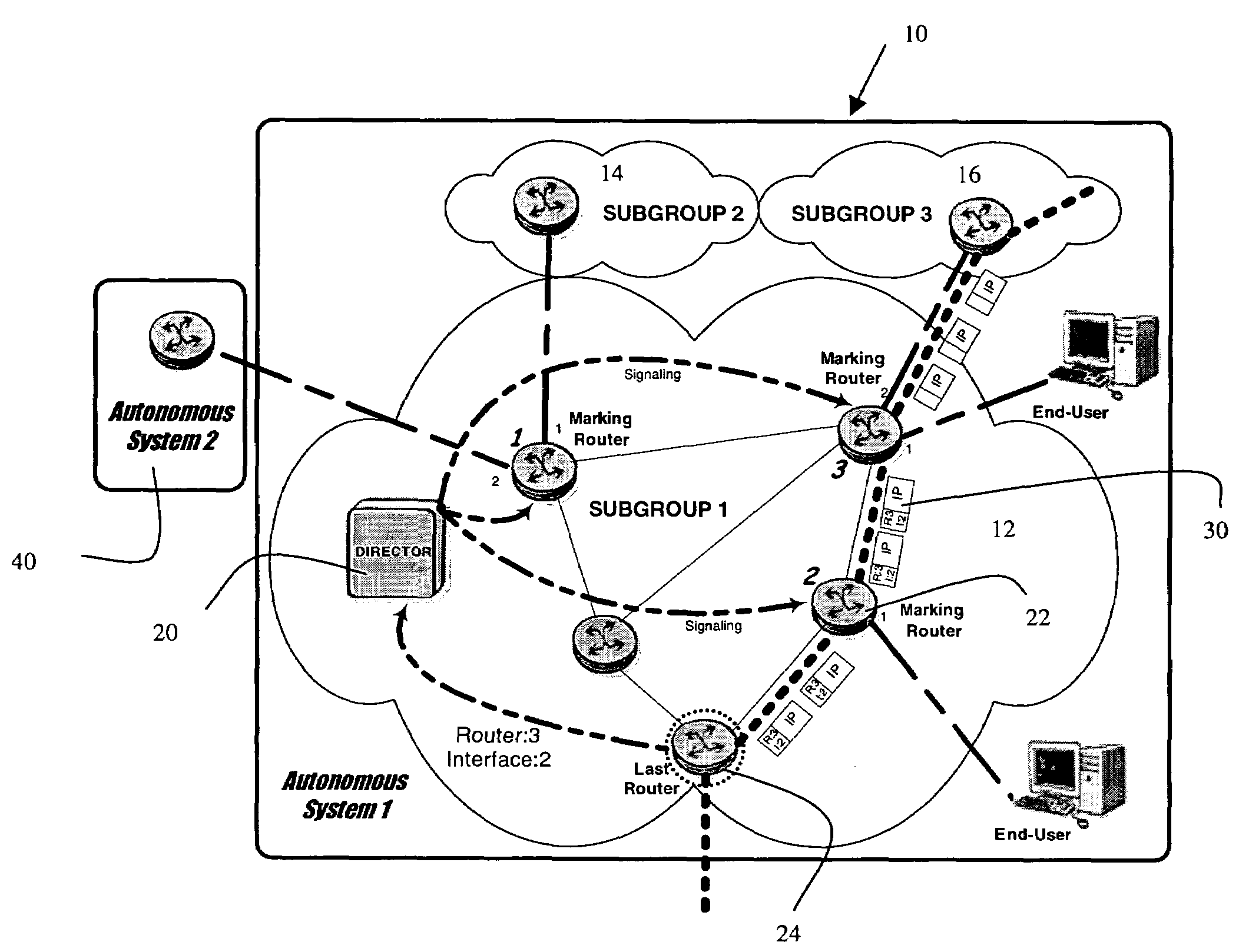
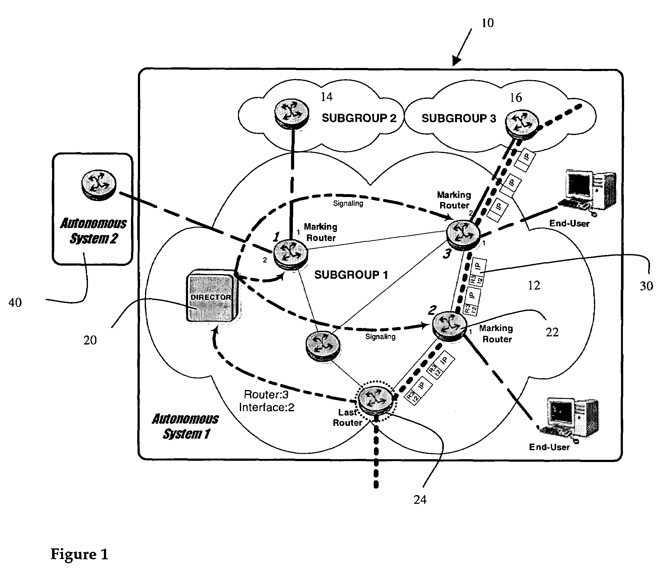
[0018]As shown in FIG. 1 the invention applies to an Autonomous System shown generally at 10. Within the Autonomous System there may be one or more subgroups shown generally as subgroup 12 subgroup 14 subgroup 16. As shown in FIG. 1 subgroup 12 has multiple routers while subgroups 14 and 16 only show a single router. It is to be understood, of course, that subgroups 14 and 16 are likely to have multiple routers as well.

[0019]Within subgroup 12 there is shown a new element known as a Director 20—an entity detached from any subgroup—which has a full and complete vision of the AS networks topology. In the case of an Autonomous System running a Link State routing protocol like OSPF (Open Shortest Path First), every router participating in the routing session has this vision for its Area. The Director 20 is able to exchange information with any router in the Autonomous System.

[0020]The Autonomous System as shown comprises a network of routers 22 connected together to carry traffic from a...


PUM


Abstract

A system and method of tracing network flows in an autonomous communications system are described. The Autonomous System may be formed of multiple subgroups depending on size and application. Each subgroup contains multiple, interconnected routers which participate in transporting data flow across the Autonomous System (AS). A Director within the AS has a full and complete vision of the network topology. When it is desired to trace a particular flow because of an identified attack, selected routers in key locations—through which that particular flow travels—mark packets with labels which enable the tracing of the path. These labels permit the source of the attack, at least in so far as it travels through the AS, to be identified. If the number of entry (or key) points to the AS is larger than the number of available labels, the AS will be divided into subgroups, the flow is traced from subgroup to subgroup.

Description

FIELD OF THE INVENTION[0001]This invention relates to wide area communications systems and more particularly to an apparatus and method for tracing network flows in such communications systems.BACKGROUND[0002]Global-based communications networks such as the Internet have evolved from an early, research-based system with limited access, to a truly world wide network with millions of users. The original network protocol, TCP / IP, was designed on the basis that system users would connect to the network for strictly legitimate purposes. As a consequence, no particular consideration was given to security issues. In recent years, however, the incidence of malicious attacks on the Internet has grown to an alarming proportion. These attacks, which take on a variety of forms, often lead to a complete disruption of service for a targeted victim.[0003]One such attack is based on the concept of flooding a victim with so much traffic that the victim's server cannot cope, or with very effective ma...

Claims


Application Information

Patent Timeline
Patent Type & Authority Patents(United States)
IPC IPC(8): G06F15/173G06F11/00H04L12/26
CPCH04L12/2602H04L43/00H04L63/1408H04L63/1458H04L2463/146H04L43/026
Inventor JONES, EMANUELEROBERT, JEAN-MARC
Owner RPX CORP
Learn More