Low loss current sensor and power converter using the same

a technology of low-loss current and power converter, applied in the field of current sensors, can solve problems such as power was

Active Publication Date: 2017-02-09
MEVAY ALEX C H
View PDF5 Cites 14 Cited by
  • Summary
  • Abstract
  • Description
  • Claims
  • Application Information

AI Technical Summary

Benefits of technology

[0005]According to one aspect of the present invention, a low-loss current sensor for use with a circuit containing a capacitor to sense a current flowing into a node in the circuit is disclosed. The current sensor includes a differentiator circuit having an input connected to the circuit capacitor and adapted to generate an output signal which is proportional to the current flowing into the circuit capacitor. The novel use of a capacitive current divider allows the sensor to sense current with virtually zero dissipated energy.

Problems solved by technology

However, one problem of using a conventional current sensor is that it wastes power, which may be significant in high-efficiency converters.

Method used


Image

  • Low loss current sensor and power converter using the same
  • Low loss current sensor and power converter using the same
  • Low loss current sensor and power converter using the same

Examples


Embodiment Construction

[0017]Definitions

[0018]Switch: While the specification illustrates a metal-oxide-semiconductor field-effect transistor (MOSFET) as an exemplary switch, a switch can refer to any electrical element capable of conducting or blocking a current, such as a bipolar transistor, IGBT, relay, diode, and the like.

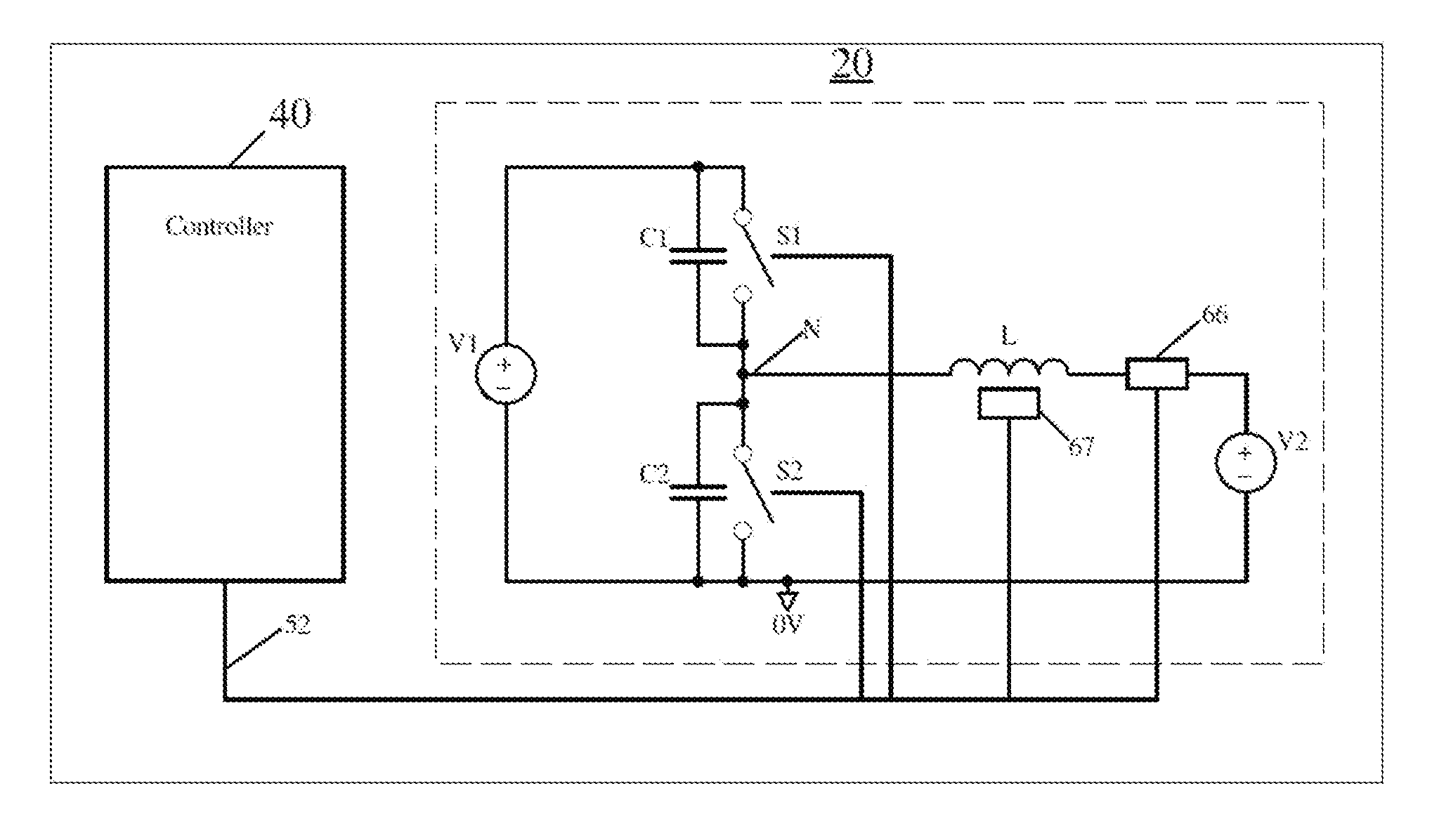
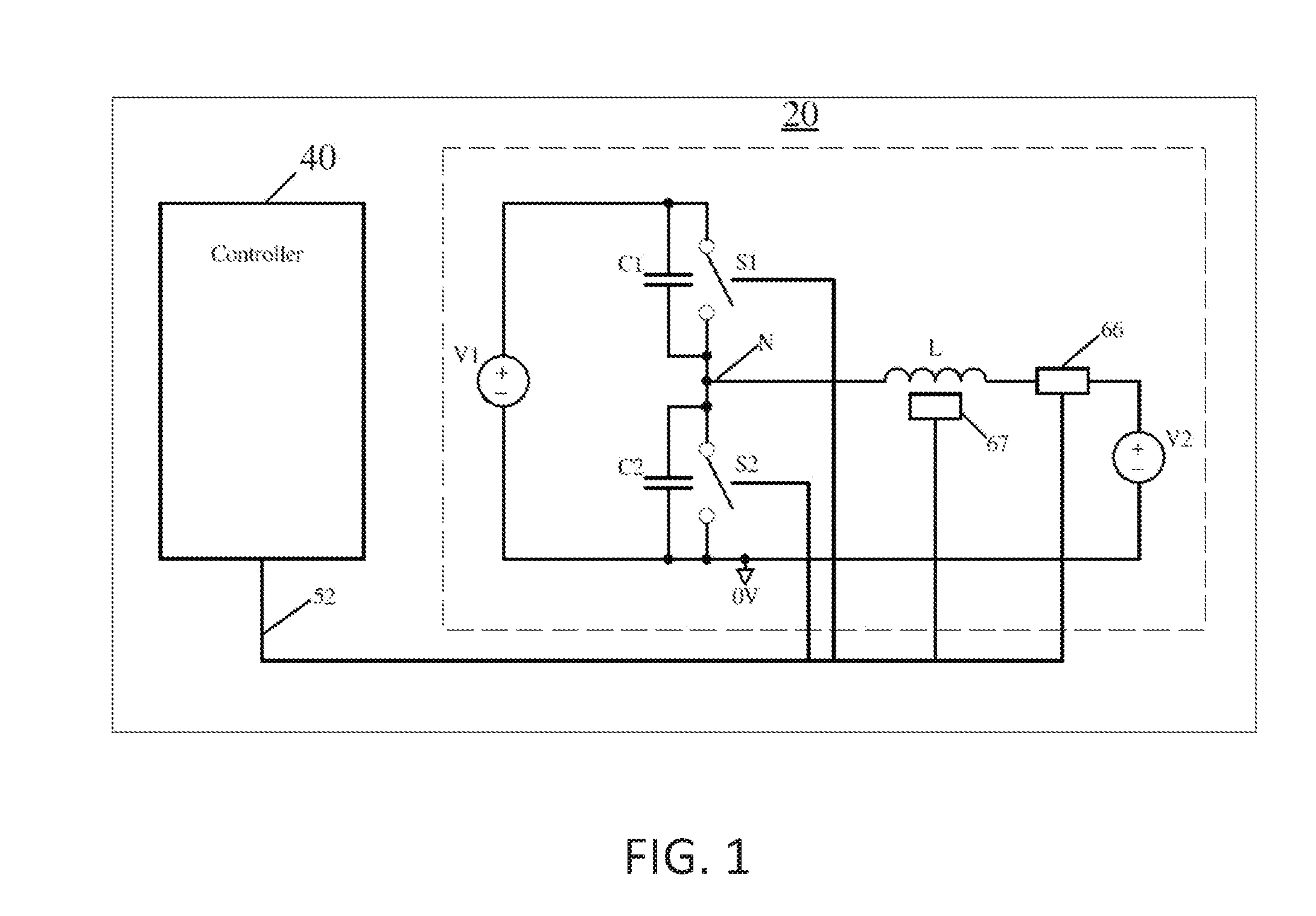
[0019]Switching node: An electrical node in the switching system at the junction of two or more switches and an inductive element or other electrical load or source.

[0020]Inductor: An explicit inductor, or the intrinsic inductance of another electrical component or circuit.

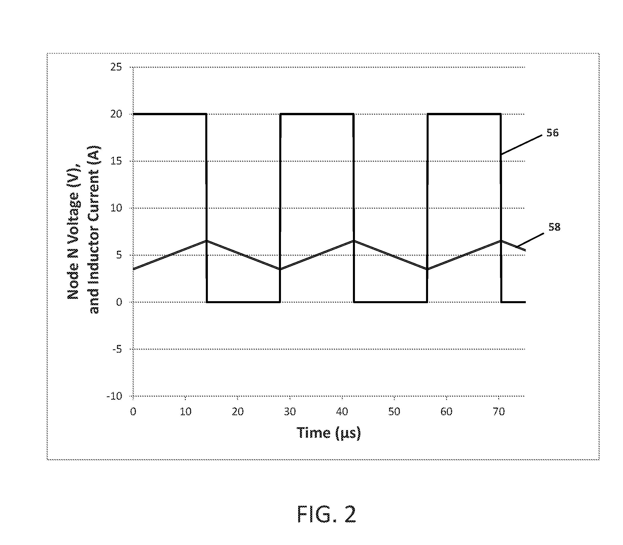
[0021]Transition time: The time during which the switching node is in between the switching potentials, determined by the inductor current, switch current(s), capacitance at the switching node, and the difference between the applicable switching potentials.

[0022]Switching potentials: The potentials between which the switching node is switched by the switches.

[0023]Controller: a processor, microcontroller or other d...


PUM


Abstract

A low-loss current sensor for use with a circuit containing a capacitor to sense a current flowing into a node in the circuit is provided. The current sensor includes a differentiator circuit having an input connected to the circuit capacitor and adapted to generate an output which is proportional to the current flowing through the circuit capacitor. The novel use of a capacitive current divider allows the sensor to sense current with virtually no power dissipation.

Description

CROSS-REFERENCE TO RELATED APPLICATION[0001]This application claims priority under 35 U.S.C. §119 to U.S. provisional patent application Ser. No. 62 / 200,194 on Aug. 3, 2015, which is incorporated by reference herein in its entirety.TECHNICAL FIELD[0002]The present invention relates to current sensors for electrical circuits containing a capacitor, and in particular current sensors for use with power converters.BACKGROUND OF THE INVENTION[0003]In electrical power converters, the measurement of current is commonly achieved by the use of a low-value shunt resistor to generate a small voltage proportional to the current flowing through the shunt resistor. This voltage is then generally amplified for further use or measurement. In a power converter, such a current sensor can be used to measure the current flowing through an inductor, which is used as a magnetic energy storage or transmission element.[0004]However, one problem of using a conventional current sensor is that it wastes power...

Claims


Application Information

Patent Timeline
Patent Type & Authority Applications(United States)
IPC IPC(8): H02M3/158G01R19/04G01R15/16H03K5/1532H02M1/08
CPCH02M3/158H03K5/1532H02M2001/0009G01R15/16G01R19/04H02M1/08H02M1/38H02M3/1588G01R31/42G01R19/0092H02M1/0009H02M7/217
Inventor MEVAY, ALEX C. H.
Owner MEVAY ALEX C H
Why Eureka
Try Eureka