Robotic interface positioning determination systems and methods

a positioning determination and robotic interface technology, applied in the field of robotic surgical systems, can solve the problems of system less precise, system less easily transportable, micro-reduction precision, etc., and achieve the effect of reducing position calculation errors and smoothing the transition

Active Publication Date: 2017-02-16
TYCO HEALTHCARE GRP LP
View PDF9 Cites 22 Cited by
  • Summary
  • Abstract
  • Description
  • Claims
  • Application Information

AI Technical Summary

Benefits of technology

[0009]Robotic surgical systems may be programmed with additional instructions and include additional non-optical sensors that supplement optical tracking sensors in the input device. The additional non-optical sensors may be configured to provide an additional range of motion for the input device that exceeds the range of motion of the optical tracking sensors. The additional programming instructions may include algorithms that reduce position calculation errors between the signals obtained from the optical and non-optical sensors. These algorithms may also provide for a smoother transition when changing the input source of the positional calculations between the optical and the non-optical sensors.

Problems solved by technology

Enlarging the joints, rods, and / or workspace made the system less easily transportable.
Upscaling the end effector motion reduced the precision of micro-movements of the end effector from ergonomically scaled motions of the input device, making the system less precise.
While an optical input device would eliminate space requirements of the mechanical rods and joints, the range of motion would still be limited by the properties and configuration of the position detectors and the light sources.
Larger ranges of motion were also supported by upscaling the end effector motion and thereby reducing the precision of the surgical system.

Method used


Image

  • Robotic interface positioning determination systems and methods
  • Robotic interface positioning determination systems and methods
  • Robotic interface positioning determination systems and methods

Examples


Embodiment Construction

[0031]Particular embodiments of the present disclosure are described herein with reference to the accompanying drawings; however, it is to be understood that the disclosed embodiments are merely examples of the disclosure and may be embodied in various forms. Well-known functions or constructions are not described in detail to avoid obscuring the present disclosure in unnecessary detail. Therefore, specific structural and functional details disclosed herein are not to be interpreted as limiting, but merely as a basis for the claims and as a representative basis for teaching one skilled in the art to variously employ the present disclosure in virtually any appropriately detailed structure. Like reference numerals may refer to similar or identical elements throughout the description of the figures.

[0032]This description may use the phrases “in an embodiment,”“in embodiments,”“in some embodiments,” or “in other embodiments,” which may each refer to one or more of the same or different ...


PUM


Abstract

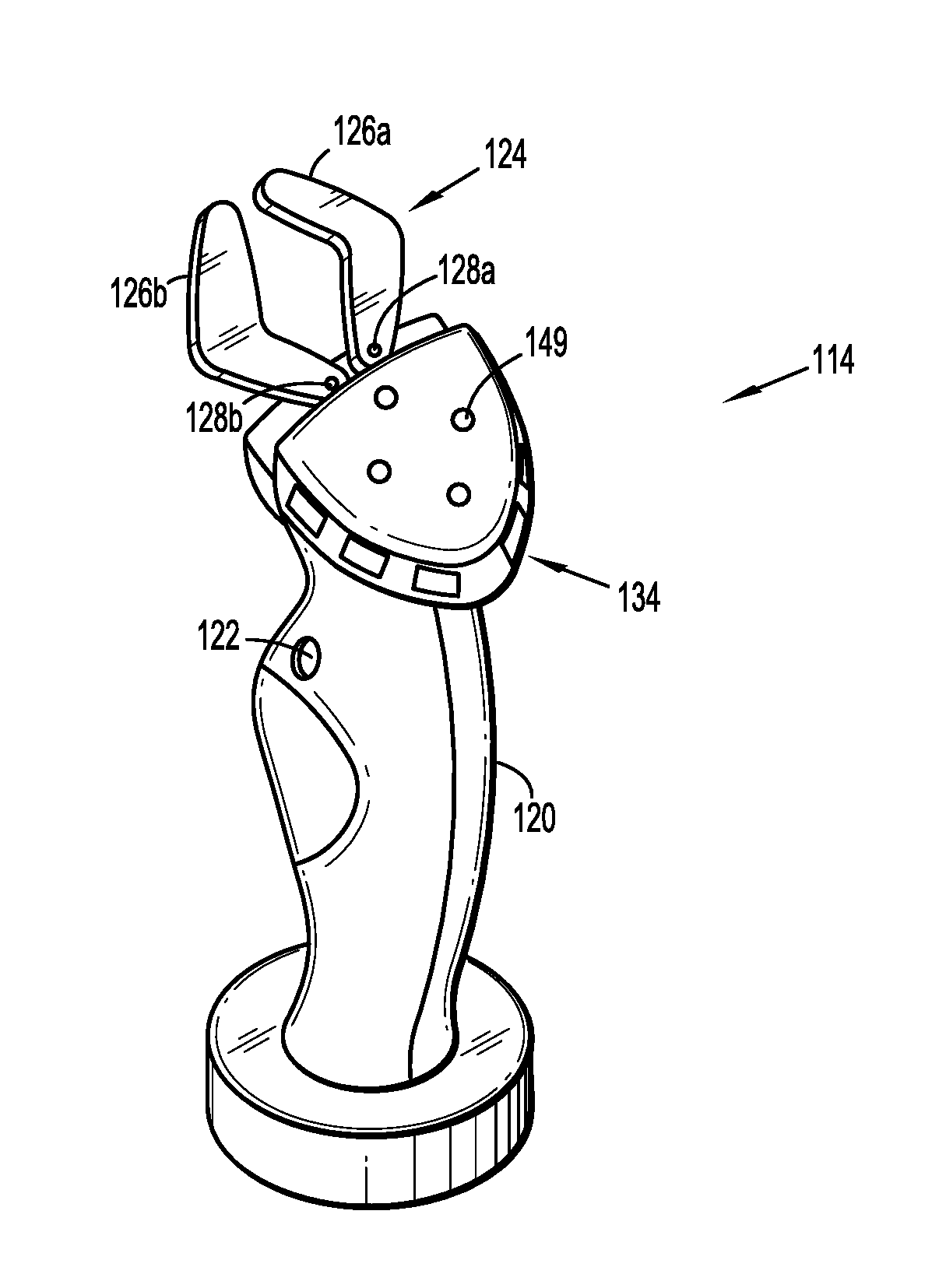
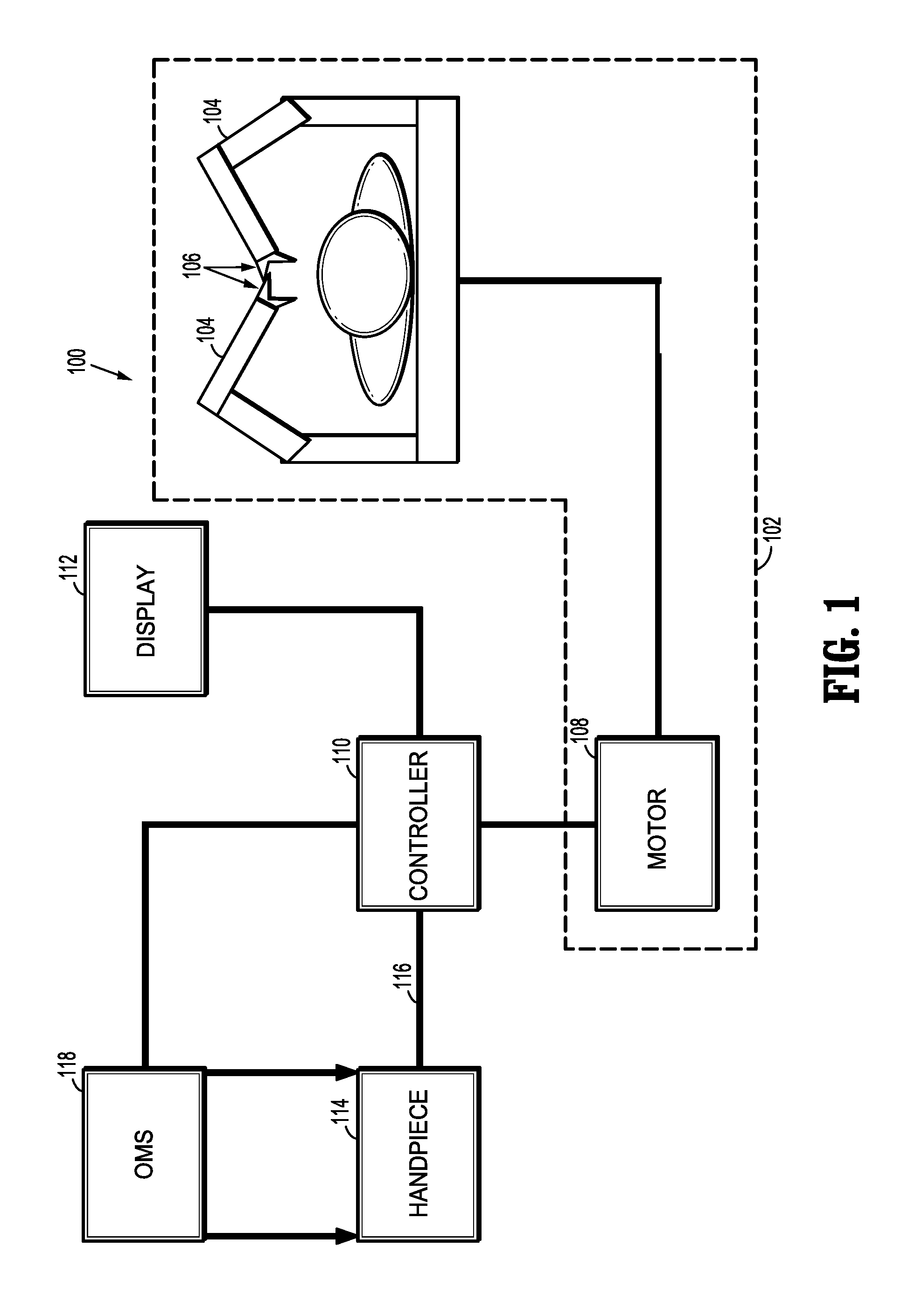
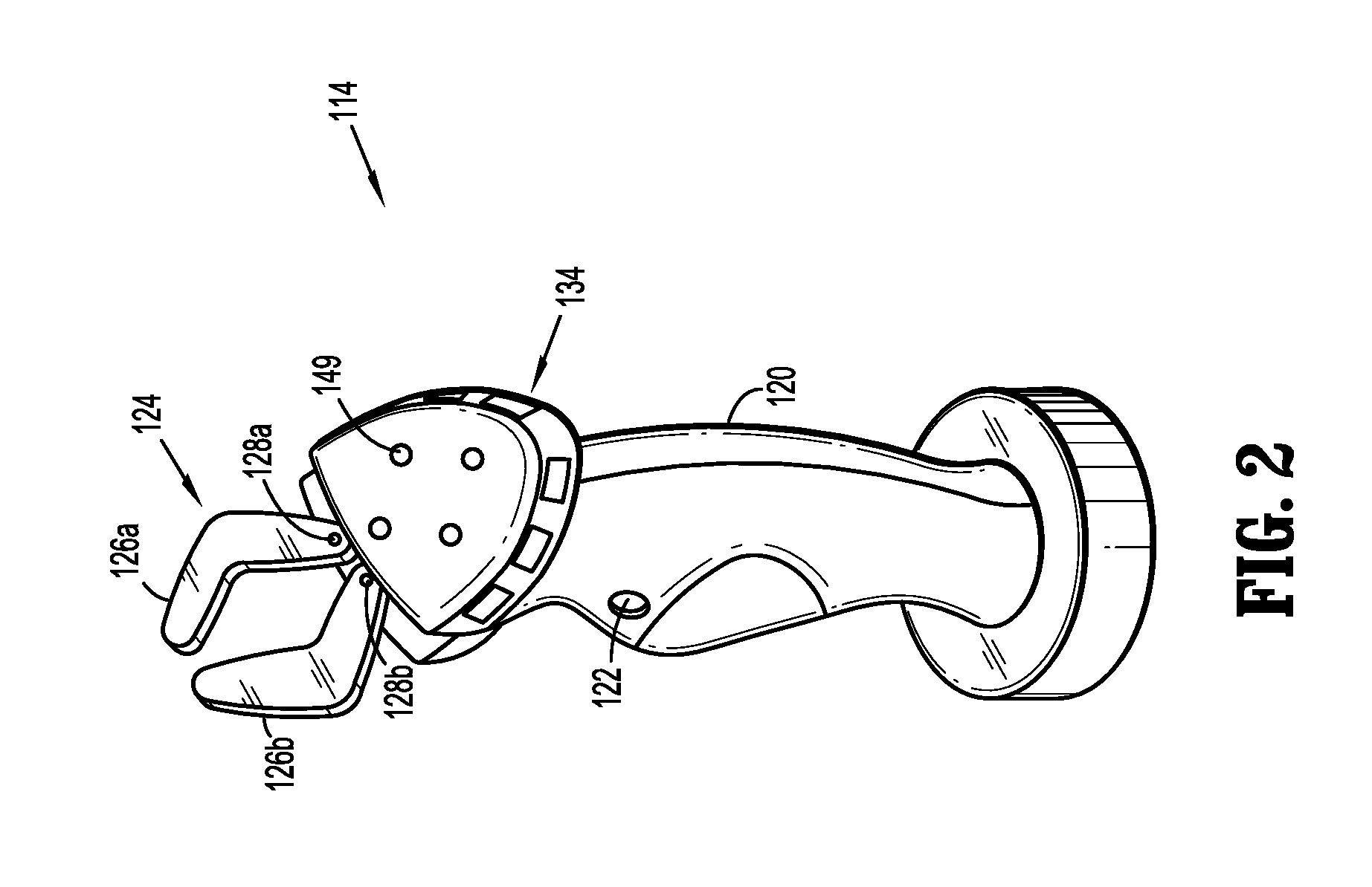
The present disclosure is directed to a robotic surgical system that includes a robotic surgical device having a robotic arm and an end effector with a pair of jaw members. A handpiece includes a pinch interface to control the arm or end effector, optical marker(s), an accelerometer, and a transmitter to transmit data from the pinch interface or accelerometer to the robotic surgical device. The system further includes a tracking system, to track the marker and provide a position or orientation of the handpiece. A processor receives: (i) the position or orientation of the handpiece from the tracking system; and (ii) the measured acceleration of the handpiece from the accelerometer. The processor integrates the measured acceleration to establish a second position beyond that of the tracking system. The processor controls movement of the robotic arm and end effector based on the received data from the camera or the accelerometer.

Description

CROSS-REFERENCE TO RELATED APPLICATIONS[0001]This application is a U.S. National Stage Application filed under 35 U.S.C. §371(a) of International Patent Application Serial No. PCT / US2014 / 069015, filed Dec. 8, 2014, which claims the benefit of U.S. Provisional Patent Application Ser. No. 61 / 983,745, filed Apr. 24, 2014, the entire disclosure of each of which are incorporated by reference herein.BACKGROUND[0002]1. Technical Field[0003]The present disclosure relates to robotic surgical systems. Particularly, the present disclosure is directed to a hand-held user interface for controlling a robotic surgical system.[0004]2. Background of the Related Art[0005]Robotic surgical systems have been used in minimally invasive medical procedures. Some robotic surgical systems included a console supporting a robot arm and a surgical instrument or end effector, such as forceps or a grasping tool, mounted to the robot arm. A mechanical input device having multiple joints was manipulated by surgeons...

Claims


Application Information

Patent Timeline
Patent Type & Authority Applications(United States)
IPC IPC(8): A61B34/37A61B90/00A61B34/00A61B34/20B25J13/02B25J9/16
CPCA61B34/37B25J13/02B25J9/1689A61B34/74A61B2090/064A61B90/06G05B2219/40132A61B2034/2048A61B2034/2055A61B34/20A61B34/30G06F3/0304G06F3/0346A61B2090/067A61B2034/2046A61B2034/2059A61B2090/0818A61B34/76A61B2017/00212A61B2017/00207A61B2034/2051
Inventor SARTOR, JOE
Owner TYCO HEALTHCARE GRP LP
Why Eureka
Try Eureka