Method and device for determining the size of a transparent particle

a technology of transparent particles and measurement methods, applied in measurement devices, particle and sedimentation analysis, instruments, etc., can solve the problems of inability to economically reasonable use of measurement methods, inconvenient measurement methods, and inaccurate geometric assumptions for the determination of size, etc., to achieve rapid and reliable particle size determination

Inactive Publication Date: 2017-02-16
TECH UNIV DARMSTADT
View PDF3 Cites 0 Cited by
  • Summary
  • Abstract
  • Description
  • Claims
  • Application Information

AI Technical Summary

Benefits of technology

[0011]One object of the present invention is therefore to create a method of the generic type defined in the introduction for determining the size of a particle, so that a reliable determination of particle size is made possible with the lowest possible structural investment.

Problems solved by technology

Although this measurement method yields good results in theory, its practical benefit is often limited.
Furthermore, the shape of the measured particles may deviate from a spherical shape, so that the geometric assumptions made for the determination of size are not correct and the values determined may differ significantly from the actual size values.
To be able to check on the reliability of the measurement results, a substantial equipment investment is required, leading in many cases to the fact that this measurement method cannot be used in an economically reasonable manner.

Method used


Image

  • Method and device for determining the size of a transparent particle
  • Method and device for determining the size of a transparent particle
  • Method and device for determining the size of a transparent particle

Examples


Embodiment Construction

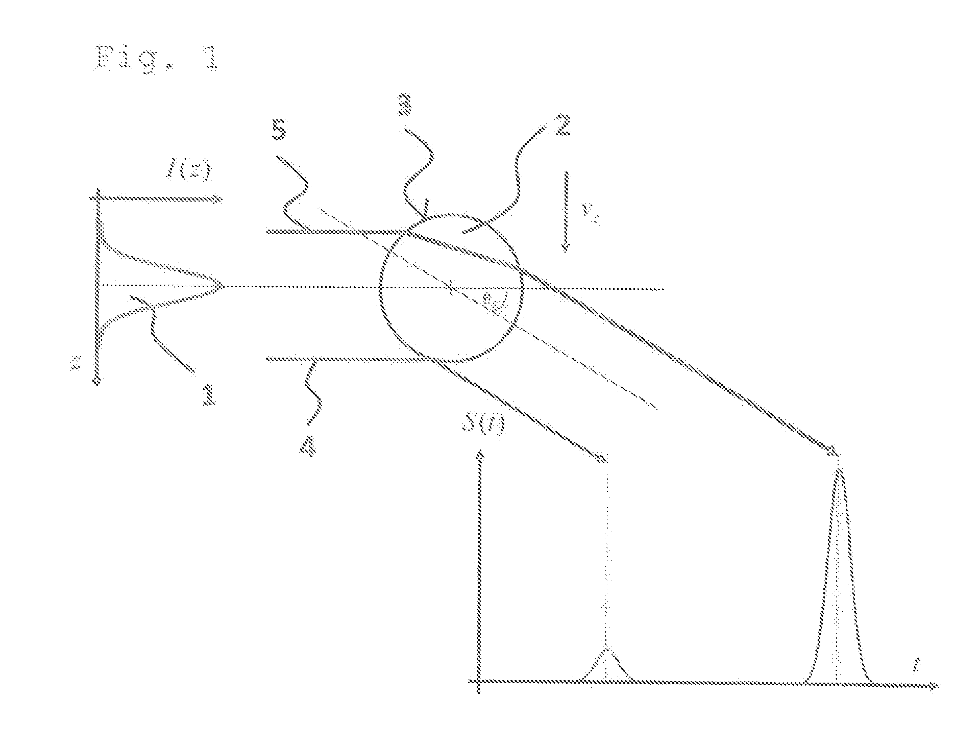
[0046]FIG. 1 shows schematically the relevant beams for determining the particle size for the method according to the invention in a scattering process in a scattering angle θs. Of a light source (not shown in FIG. 1), a beam of light 1 strikes a particle 2 which is moving through the beam of light 1 crossing through the beam of light 1. The beam of light 1 is reflected from the outside on the interface 3 of a particle 2 to the surrounding medium and transmitted through the particle 2 on emerging from the particle 2 through refraction on entrance and exit from the particle 2. FIG. 1 shows the solid-line beams for the reflection and for the transmission that occur at a predetermined scattering angle θs and can be detected. A reflection beam 4 is reflected at the interface 3. A transmission beam 5 is refracted into the interior of the particle 2 and is refracted again on emerging from the particle 2.

[0047]The respective angle of incidence θi of the solid-line beams which generate corr...


PUM

PropertyMeasurementUnit
sizeaaaaaaaaaa
scattering angleaaaaaaaaaa
refractive indexaaaaaaaaaa

Abstract

A method is described for determining the size of a transparent particle (2), wherein the particle (2) is illuminated with light from a light source (6), wherein using a radiation detector (7) a time-resolved intensity curve of light from the light source (6) scattered on the particle (2) is measured at a preselectable scattering angle θs, wherein characteristic scattered light peaks are determined in the intensity curve, and wherein the size of the particle (2) is determined on the basis of the time difference between two scattered light peaks, characterized in that, with the help of two radiation detectors (7) or light sources (6), a first and a second time-resolved intensity curve of scattered light, scattered on the particle (2) in the forward direction, are measured; a transmission peak (12) and a reflection peak (11) are determined from the first intensity curve and from the second intensity curve; a first time difference between the transmission peaks (12) is determined, and a second time difference between the reflection peaks (11) is determined; a characteristic variable α is determined from the ratio of the first time difference and the second time difference; and a size determination is performed for the particles (2) for which the characteristic variable α corresponds to a preselectable value. (FIG. 3)

Description

CROSS REFERENCE TO RELATED APPLICATIONS[0001]This application is a continuation of U.S. application Ser. No. 14 / 181,789, filed Feb. 17, 2014, which is incorporated herein by reference in its entirety and which is a continuation application of international application PCT / EP2012 / 066129, filed Aug. 17, 2012 designating the United States and claiming priority to Germany applications DE 10 2011 052 783.4, filed Aug. 17, 2011 and DE 10 2012 102 363.8, filed Mar. 20, 2012.BACKGROUND OF THE INVENTION[0002]The invention relates to a method for determining the size of a transparent particle, wherein the particle is illuminated with light from a light source, wherein a time-resolved intensity curve of light from the light source scattered on the particle is measured with a radiation detector at a preselectable scattering angle θs, wherein characteristic scattered light peaks are determined in the intensity curve and the size of the particle is determined on the basis of a time difference bet...

Claims


Application Information

Patent Timeline
Patent Type & Authority Applications(United States)
IPC IPC(8): G01N15/02
CPCG01N15/0211G01N2015/0238G01N2015/0222G01N15/0205G01N15/1434G01N21/4133G01N2015/1493G01N2201/0621
Inventor TROPEA, CAMERONSCHAEFER, WALTER
Owner TECH UNIV DARMSTADT
Why Eureka
Try Eureka