
Electronic device and method for controlling fan of electronic device

a technology of electronic devices and electronic devices, which is applied in the direction of battery overheat protection, safety/protection circuits, instruments, etc., can solve problems such as noise, and achieve the effects of preventing power from being wasted, reducing resources that are required, and preventing a temperature rise of electronic devices

Active Publication Date: 2017-02-16
SAMSUNG ELECTRONICS CO LTD
View PDF4 Cites 262 Cited by
  • Summary
  • Abstract
  • Description
  • Claims
  • Application Information

AI Technical Summary

Benefits of technology

The present invention relates to a charging device and an electronic device that can communicate with each other. The charging device can adjust the amount of power transmitted based on the charging configuration information received from the electronic device. This helps to prevent power wastage and minimize resource usage. Additionally, the driving speed of a fan can be adjusted based on the amount of power to prevent temperature rise and minimize noise.

Problems solved by technology

The driving of a fan to transfer the radiated heat to the outside may also bring about noise.

Method used


Image

  • Electronic device and method for controlling fan of electronic device
  • Electronic device and method for controlling fan of electronic device
  • Electronic device and method for controlling fan of electronic device

Examples


Embodiment Construction

[0030]Hereinafter, various embodiments of the present document will be described with reference to the accompanying drawings. However, it should be understood that there is no intent to limit the present disclosure to the particular forms disclosed herein; rather, the present disclosure should be construed to cover various modifications, equivalents, and / or alternatives of embodiments of the present disclosure. In describing the drawings, similar reference numerals may be used to designate similar constituent elements.

[0031]In the present disclosure, the expression “have”, “may have”, “include” or “may include” refers to existence of a corresponding feature (e.g., numerical value, function, operation, or components such as elements), and does not exclude existence of additional features.

[0032]In the present disclosure, the expression “A or B”, “at least one of A or / and B”, or “one or more of A or / and B” may include all possible combinations of the items listed. For example, the expr...


PUM


Abstract

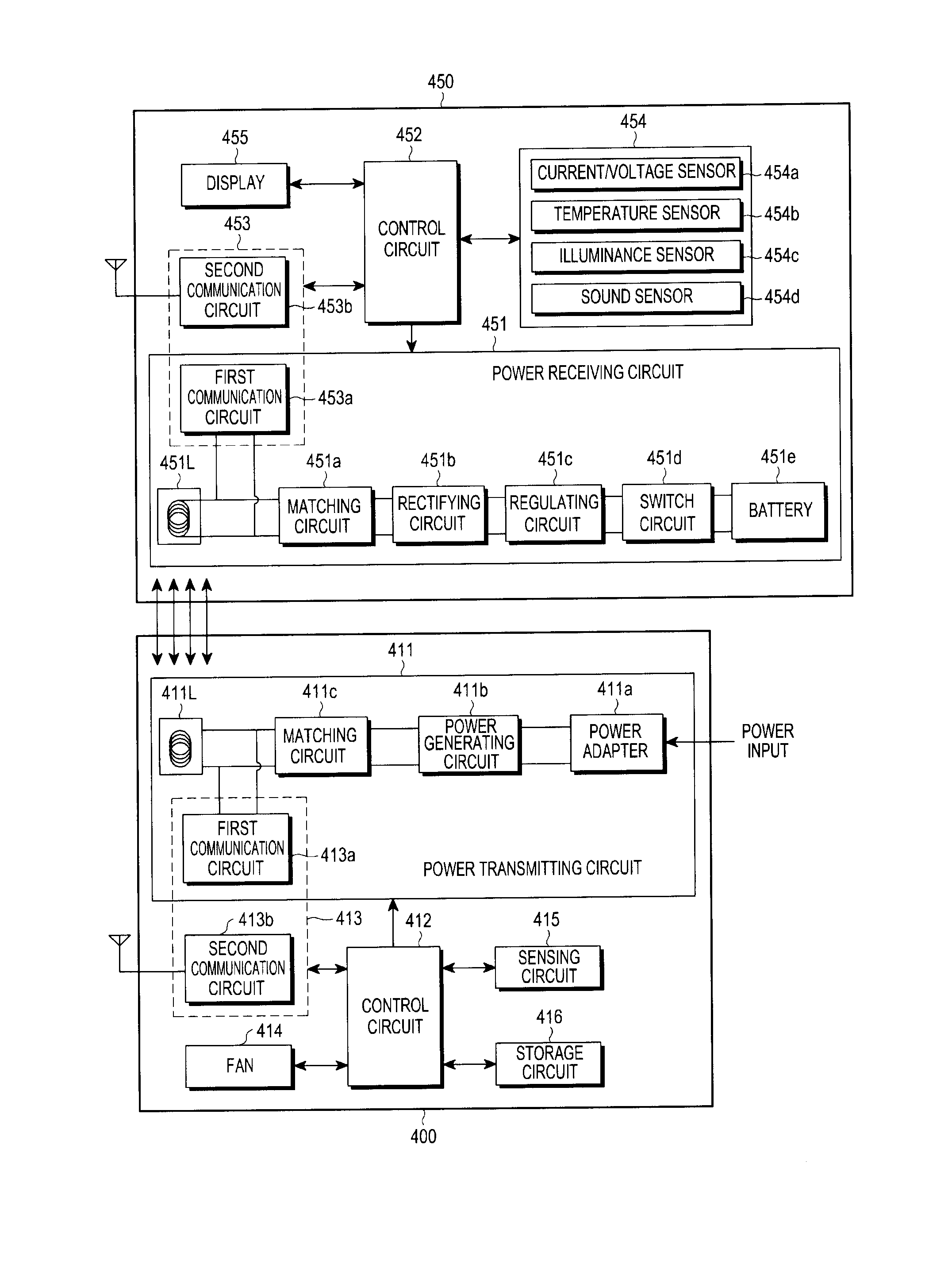
According to various embodiments, an electronic device for charging a battery of an external device may include a coil and a first circuit configured to wirelessly transmit power to the external device through the coil. A second circuit may be configured to wirelessly receive information from the external device. A fan may be disposed adjacent to the coil to discharge heat to the exterior of the electronic device. A control circuit may adjust the driving speed of the fan based at least in part on the received information.

Description

CLAIM OF PRIORITY[0001]This application claims the priority under 35 U.S.C. §119(a) to Korean Application Serial No. 10-2005-0114161, which was filed in the Korean Intellectual Property Office on Aug. 12, 2015, the entire content of which is hereby incorporated by reference.TECHNICAL FIELD[0002]The present disclosure relates generally to wireless charging, and, more particularly, to an electronic device in a wireless charging system, and a fan control method of the electronic device.BACKGROUND[0003]Mobile terminals, such as mobile phones or PDAs (Personal Digital Assistants), are driven by a rechargeable battery according to their features, and, in order to charge the battery, electrical energy is supplied to the battery of the mobile terminal by a separate charging device. Typically, the charging device and the battery have separate contact terminals, respectively, which allows the charging device and the battery to be electrically connected to each other by bringing the charging d...

Claims


Application Information

Patent Timeline
Patent Type & Authority Applications(United States)
IPC IPC(8): H02J50/12H02J7/02H05K7/20H02J50/60
CPCH02J50/12H02J50/60H05K7/20136H05K7/20209H02J7/025H02J50/80H02J50/00H02J7/00032H02J7/00034H05K7/20945H05K7/20909H02J7/00309G06F1/206G06F1/26
Inventor JUNG, KU-CHULKOO, KYUNG-HAPARK, CHUL-WOOJANG, KI-YOUNYUN, YONG-SANGCHO, CHI-HYUN
Owner SAMSUNG ELECTRONICS CO LTD
Learn More