Eureka AIR delivers breakthrough ideas for toughest innovation challenges, trusted by R&D personnel around the world.

System and method for dynamic bandwidth allocation on PONs

a dynamic bandwidth and allocation technology, applied in the field of communication, can solve the problems of limiting the size reduction of the ont, unnecessarily high power consumption, and limitations of the known ont, and achieve the effect of reducing the size of the on

Inactive Publication Date: 2008-06-10
IKANOS COMMUNICATIONS
View PDF10 Cites 61 Cited by
  • Summary
  • Abstract
  • Description
  • Claims
  • Application Information

AI Technical Summary

Benefits of technology

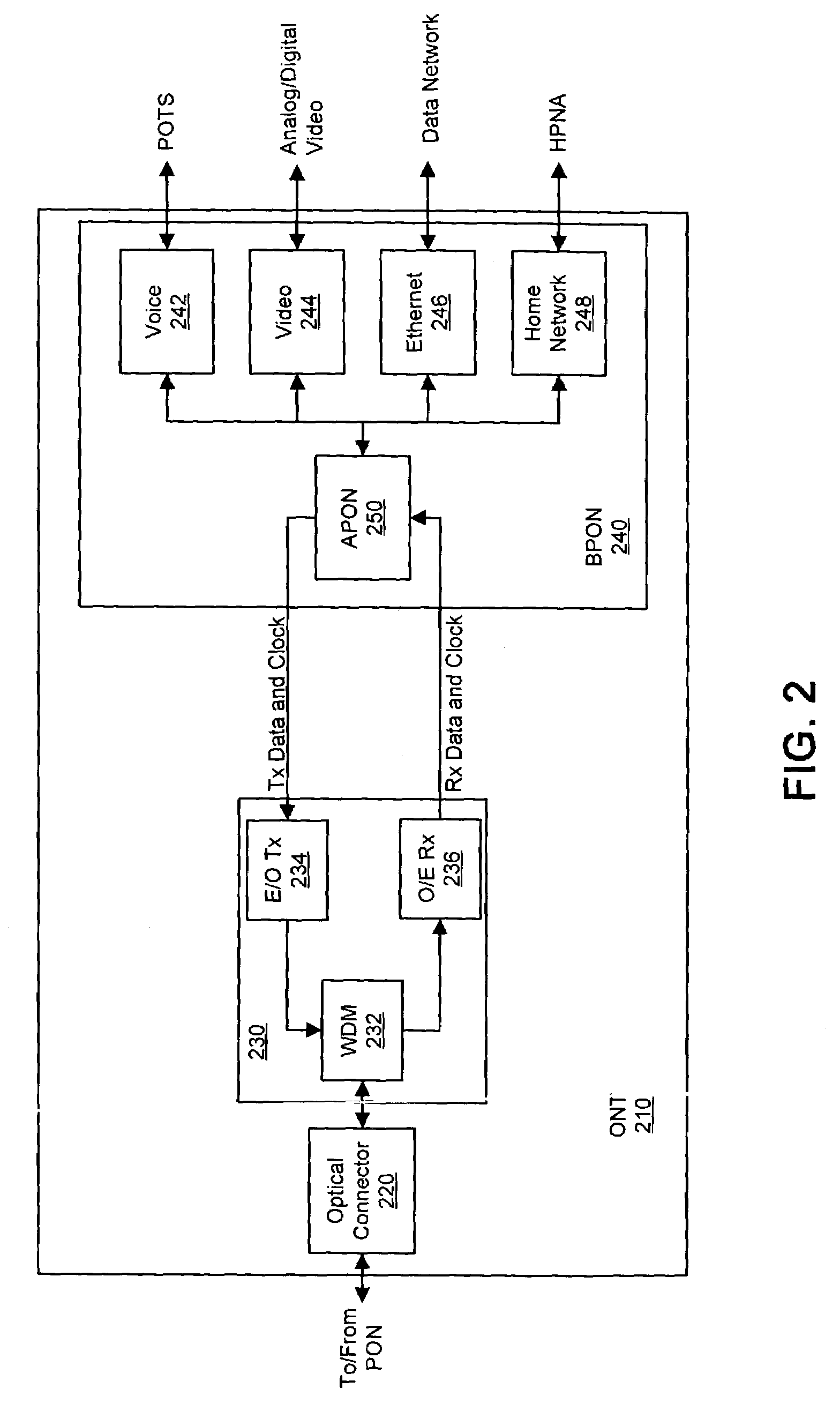
[0020]Various embodiments of the present invention provide an integrated PON / Voice / Communications processor in accordance with the ITU G.983.X Recommendation. The implementation methods and level of integration can be chosen to minimize cost and optimize performance of a broadband passive optical network termination (ONT) device. One objective of the present invention is to reduce the development cost of an ONT. Another objective includes reducing net power consumption for the aggregate functionality required for broadband voice, video, and data service. Yet another objective is to provide a scaleable and flexible PON optics interface capable of multiple symmetric / asymmetric configurations. An additional objective of the present invention is to provide scaleable upstream and downstream burst buffering to allow real time bandwidth control / allocation (minimize cell loss ratio versus load, delay versus system load) across the PON. The present invention finds particular beneficial implementation in the FTTB (Fiber to the Business) and FTTH (Fiber to the Home) markets.
[0022]By integrating the described functionality onto a single chip, the following advantages may be realized: lower ONT power consumption as interfaces between multiple processors can be better controlled; memory resource sharing among multiple processors reduces power consumption, reduces resource duplication and reduces total system cost; lower electromagnetic interference (EMI) levels as signal loop areas are reduced since fewer high signal level interfaces and interconnects are required; higher reliability as fewer components and less PCB area are required; improved system diagnostics capability as functions such as self tests and loop backs can be easily included and controlled; and ONT suppliers can stock less overall component inventory per ONT.

Problems solved by technology

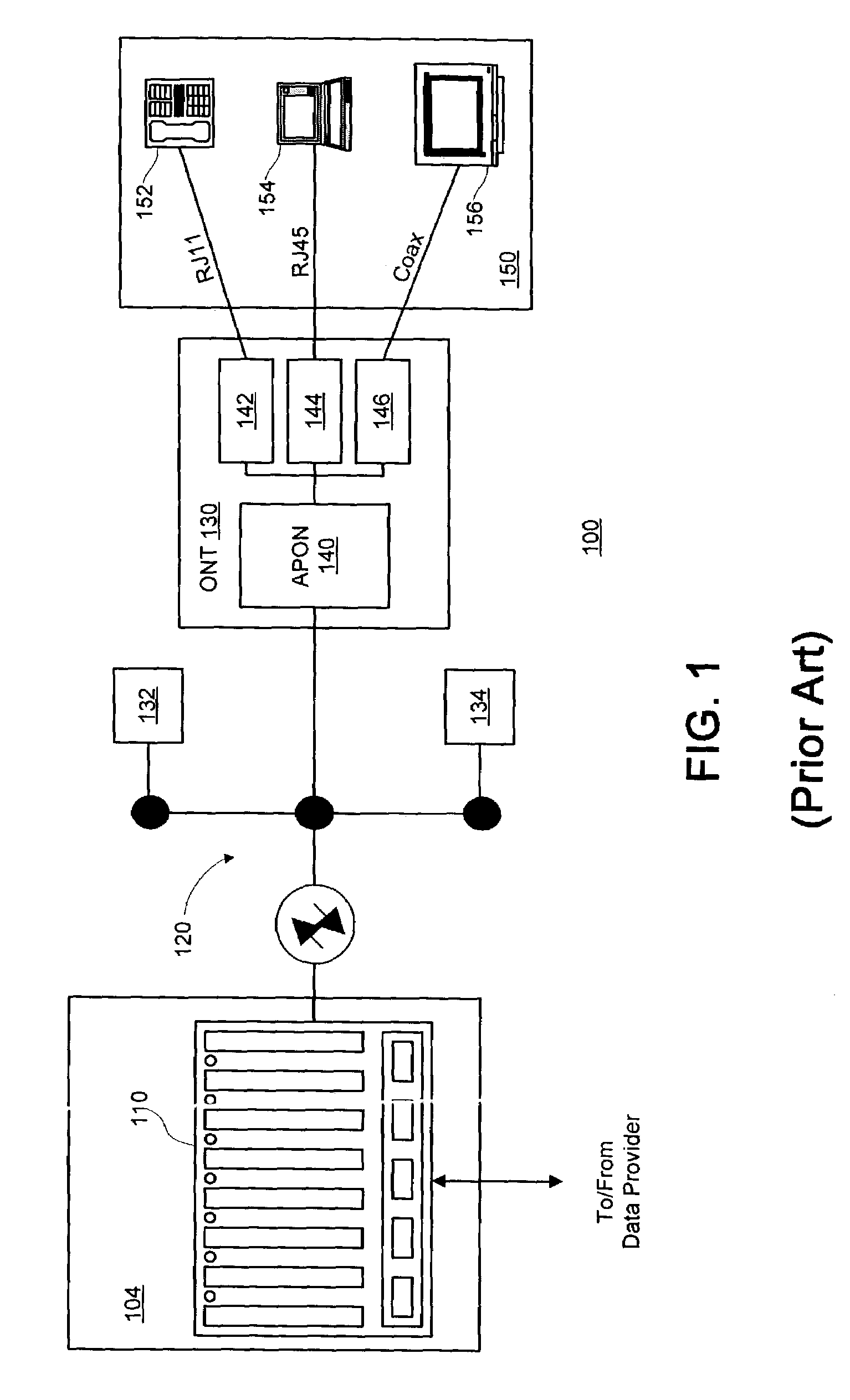
While the use of optical network terminations (ONTs), also known as network interface devices (NIDs) or optical network units (ONUs), in passive optical networks provides a great deal of flexibility in data content, data transmission rates, and other design considerations, known ONTs have a number of limitations.
For one, the use of separate devices on a PCB limits the reduction of the size of the ONT.
Additionally, utilizing separate devices to provide PON processing functionality results in unnecessarily high power consumption, as the interfaces between the devices results in power loss due to parasitic capacitance, current leak, poorly controlled interfaces between the devices, and the like.
Likewise, the signal loops on the PCB and the interconnects produce a relatively large amount of electromagnetic interference (EMI) which can interfere with the operation of the ONT.
Similarly, the connections between devices and PCBs and the traces between the devices of the PCB often are somewhat unreliable, so by implementing a relatively large number of devices to provide PON processing functionality, the reliability of the ONT can be compromised.
Another limitation is resource duplication between the devices, since each device often implements some common functionalities, such as memory, memory access controllers, registers, and the like.
In addition to the limitations of the physical structure of known ONTs, PON standards, such as the ITU G.983.X Recommendation, are deficient in a number of areas.
For example, the ITU G.983.X Recommendation provides for a rudimentary data protection method referred to “churning.” However, the churning key used in accordance with the G.983.X Recommendation is only 24 bits long, a key length that is recognized by those skilled in the art as relatively weak.

Method used


Image

  • System and method for dynamic bandwidth allocation on PONs
  • System and method for dynamic bandwidth allocation on PONs
  • System and method for dynamic bandwidth allocation on PONs

Examples


Embodiment Construction

[0033]In the interest of brevity, a number of acronyms, initialisms, and abbreviations may be used in the following discussion. To provide a useful reference, these terms and their corresponding representation are listed below:

[0034]

ADSLAsymmetric Digital Subscriber LineAPONATM Over Passive Optical NetworkATMAsynchronous Transfer ModeBERBit Error RateBFPBack Facet PhotodiodeBIPByte Interleaved ParityBM LDRBurst Mode Laser DriverPONBroadband Over Passive Optical NetworkCATVCoaxial Cable TelevisionCLECCompetitive Local Exchange CarrierCOCentral OfficeCM AGCContinuous Mode Automatic Gain ControlCM CDRContinuous Mode Clock & Data RecoveryCM TIAContinuous Mode Trans-Impedance AmplifierCRCCyclic Redundancy CheckDBADynamic Bandwidth AllocationDFBDistributed Feedback LaserDSDownstreamDSLDigital Subscriber LineDWDMDense Wavelength Division MultiplexingEMIElectro-Magnetic InterferenceEMSElement Management SystemE / OElectrical to OpticalEPBExtended Peripheral BusEPONEthernet Over Passive Optica...


PUM


Abstract

Mechanisms for providing a subscriber-side interface with a passive optical network are described herein. An optical network termination (ONT) having an integrated broadband passive optical network processor is utilized to receive downstream data from an optical line termination (OLT) via a passive optical network and provide the contents of the downstream data to one or more subscriber devices via one or more data interfaces. Similarly, the ONT is adapted to receive and transmit upstream data from the one or more subscriber devices to the OLT via the passive optical network. The ONT preferably implements one or burst buffers for buffering upstream and / or downstream data. The ONT can be adapted to notify the OLT of the status of the burst buffer, thereby allowing the OLT to modify the bandwidth allocations.

Description

FIELD OF THE INVENTION[0001]The present invention relates generally to communication using broadband passive optical networks and more particularly to buffering data in passive optical networks.BACKGROUND OF THE INVENTION[0002]A number of network technologies have been developed for connecting the so-called “last mile” between a central office and subscriber. One such development is the passive optical network (PON). PONs typically include a fiber optic network between a central office (CO) and a subscriber comprising active network devices only at the CO and at the subscriber premises. As such, PONs generally require less power to operate, are more reliant, and can be upgraded without having to upgrade the plant between the CO and the subscriber.[0003]PONs often are used to provide multiple types of data content, such as voice, data, and video, over the same network. To properly distribute this content, a number of common network protocols, such as Ethernet and Asynchronous Transfe...

Claims


Application Information

Patent Timeline
IPC IPC(8): H04L12/56H04J3/16H04L12/28H04L29/06
CPCH04J3/1682H04J3/1694H04L63/0428H04Q11/0067H04Q2011/0064
Inventor STISCIA, JAMESCHEN, RAYMOND
Owner IKANOS COMMUNICATIONS
Why Eureka
Eureka Blog
Learn More