

Injection molding apparatus
- Summary
- Abstract
- Description
- Claims
- Application Information
AI Technical Summary
Benefits of technology
Problems solved by technology
Method used
Image

Examples
Embodiment Construction
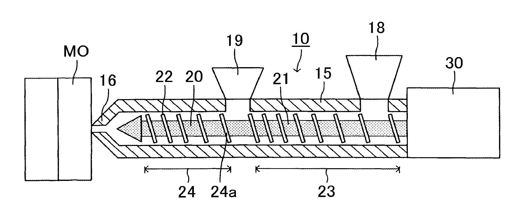
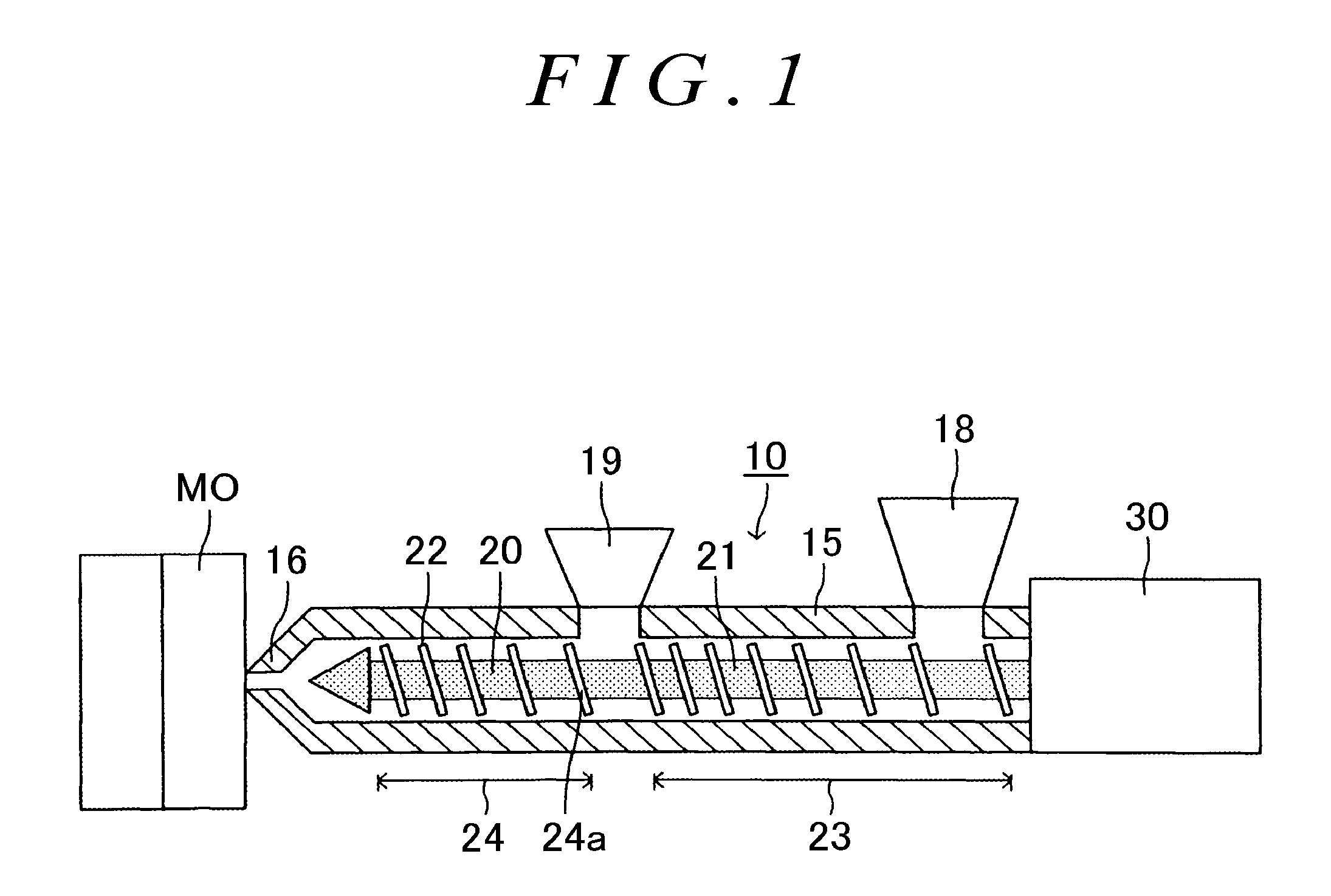
[0018]One embodiment of the present invention will be described below with reference to the drawings. An injection molding apparatus 10 of the present embodiment has the following structure. As illustrated in FIG. 1, the injection molding apparatus 10 of the present embodiment includes, as large constituents, an injection cylinder 15, a primary hopper 18, a secondary hopper 19, a screw 20 disposed inside the injection cylinder 15, and a drive unit 30.
[0019]The injection cylinder 15 is a generally cylindrical member extending linearly. A nozzle 16 is attached to a tip opening (a left end in FIG. 1) of the injection cylinder 15. The nozzle 16 is connected to a molding die MO, and the nozzle 16 communicates with a cavity in the molding die MO. A heater (not shown) is attached to the injection cylinder 15.
[0020]As illustrated in FIG. 1, the primary hopper 18 (an example of a resin supply portion) and the secondary hopper 19 (an example of a reinforced fiber supply portion) are fixed to ...
PUM
| Property | Measurement | Unit |
|---|---|---|
| Depth | aaaaa | aaaaa |
Abstract
Description
Claims
Application Information